Component diagram
| UML diagram types |
|---|
| Structural UML diagrams |
| Behavioral UML diagrams |
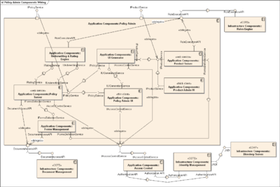
In Unified Modeling Language (UML), a component diagram depicts how components are wired together to form larger components or software systems. They are used to illustrate the structure of arbitrarily complex systems.
Overview
A component is something required to execute a stereotype function. Examples of stereotypes in components include executables, documents, database tables, files, and library files.
Components are wired together by using an assembly connector to connect the required interface of one component with the provided interface of another component. This illustrates the service consumer - service provider relationship between the two components.
An assembly connector is a "connector between two components that defines that one component provides the services that another component requires. An assembly connector is a connector that is defined from a required interface or port to a provided interface or port."[1]
When using a component diagram to show the internal structure of a component, the provided and required interfaces of the encompassing component can delegate to the corresponding interfaces of the contained components.
A delegation connector is a "connector that links the external contract of a component (as specified by its ports) to the internal realization of that behavior by the component’s parts."[1]
The example above illustrates what a typical insurance policy administration system might look like. Each of the components depicted in the above diagram may have other component diagrams illustrating its internal structure.
Arthurian Approach
In the arthurian approach the system is analyzed from above not emphasizing any specific component. This approach allows for the usage of a smaller number of less detailed diagrams that still describe the system fairly accurately. It is very useful in the early stages of a project given that these diagrams are easier to change as the project develops and matures.
Symbols
A component is represented by a rectangle with either the keyword "component" or a stereotype in the top right corner: a small rectangle with two even smaller rectangles jutting out on the left.[2]
The lollipop, a small circle on a stick, represents an implemented or provided interface. The socket symbol is a semicircle on a stick that can fit around the lollipop. This socket is a dependency or needed interface.[3]
References
- 1 2 OMG Unified Modeling Language (UML), Superstructure, V2.1.2, p.154.
- ↑ OMG Unified Modeling Language (UML), V2.5, p.208.
- ↑ Ambler, Scott W. "Introduction to UML 2 Component Diagrams". Retrieved 16 September 2012.
External links
| Wikimedia Commons has media related to Component diagrams. |
- Component Diagrams in UML 2
- UML 2 Component Diagram Guidelines by Scott W. Ambler
- UML 2 Component Diagrams
| Actors |
|  | |||||||||||
|---|---|---|---|---|---|---|---|---|---|---|---|---|---|
| Concepts |
| ||||||||||||
| Diagrams |
| ||||||||||||
| Derived languages | |||||||||||||
| Other topics | |||||||||||||