Common Berthing Mechanism

The Common Berthing Mechanism (CBM) is a berthing mechanism primarily used to connect pressurized elements within the US Orbital Segment of the International Space Station. It roughly corresponds to the docking ports that are used to join such elements within the Russian Orbital Segment. It was developed by Boeing at the Marshall Space Flight Center (MSFC) in Huntsville, Alabama under contract NAS15-10000 from the National Aeronautics and Space Administration (NASA).[1]
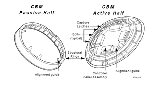
The CBM system is a combination of structural, mechanical and control components that perform the capture, closure, and passive structural connection between two pressurized modules. The total CBM system is composed of two distinct sets of equipment: the active and passive halves. The active half [ACBM] supports the mechanical and control elements which effect the actual capture and closure functions of the berthing operations. The passive half [PCBM] contains the inert elements required to complete the berthing and closure action. It also contains the seals effecting pressurized capability at the Module/Module interface.[2]
The ACBM was developed in response to specification S683-29902 (CAGE 3A768). The PCBM was developed under specification S683-28943 (CAGE 3A768). According to the specifications, the CBM provides a Module/Module clear passage diameter of 50"[3], which is large enough to accommodate a standard hatch and allow International Standard Payload Racks to be passed between modules. Using such racks, payloads can be pre-configured and transported to the station aboard a variety of logistics modules. Once the hatches have been opened and the Module/Module vestibule configured, electrical, data, and fluid lines can be manually connected by the crew in a "shirt-sleeve" environment.
In addition to Module/Module attachment locations, the CBM is also used as a structural/mechanical/utility interface (e.g., for the base of the Z1 truss) and for docking adapters at various locations.
Operation
On radial ports, the 4 covers ('petals') on the ACBM open to expose the 4 sets of latches and alignment guides. For any ACBM location, the PCBM is aligned with ACBM using a tele-robotic device (of which several varieties exist). Latches engage and retract. When fully latched, 16 bolts are driven (under remote control) from the active side into the passive side. Bolts are tightened in multiple stages, allowing the temperatures to equalise as necessary. Bolt loads are sensed by a load cell within each of the 16 units.
Use on ISS
The first modules in space using the CBM were Unity and the Pressurized Mating Adapters PMA-1 and PMA-2, with all three being launched attached together aboard Endeavour. The first berthing in space using the CBM was the connecting of the Z1 truss to Unity on the International Space Station.[1]
The CBM has been used as a berthing mechanism for the STS-transported Multi-Purpose Logistics Modules and the unmanned Japanese H-II Transfer Vehicle (HTV), SpaceX Dragon, and Orbital Sciences' Cygnus spacecraft. These spacecraft feature a PCBM, and are berthed to one of the station's open ACBMs using the station's robot arm.[4]
Each CBM compatible module that connects to previously launched modules requires a PCBM to connect to an ACBM.[1] The three ISS connecting nodes feature four radial ACBM ports. Unity features two ACBM on the ends, while Harmony and Tranquility feature a PCBM on one end and an ACBM on the other end.[5][6] The Destiny' laboratory and the Japanese Pressurised Module both feature one PCBM and one ACBM.[7][8]
Gallery
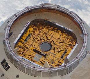 A passive CBM (as on Dragon)
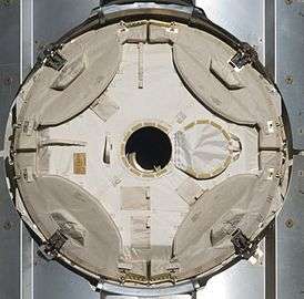 An active CBM with covers closed
 Quadrant photograph of the Active Common Berthing Mechanism in the Assembly Level Qualification Test
See also
| Wikimedia Commons has media related to Common Berthing Mechanism. |
References
- 1 2 3 Honeywell (2001). "The common berthing mechanism (CBM) for International Space Station" (PDF). (923 KiB)
- ↑ CAGE 3A768: T683-13850-3, "Common Berthing Mechanism Assembly Qualification Test Report (Revision New)" (8 October 1998)
- ↑ CAGE 3A768: S683-28943C: "Passive Common Berthing Mechanism Critical Item Development Specification" (21 July 1995).
- ↑ Commercial Crew and Cargo Program : COTS : Overview
- ↑ Gualtieri, N; Rubino, S.; Itta, A. SM98-110/254 International Space Station Node 2 – Structure Design Analysis and Static Test Definition. European Space Agency. p. 174. ISBN 92-9092-712-7.
- ↑ "Node 3 Description" (PDF). NASA. Archived from the original (PDF) on 2006-09-29.
- ↑ "STS-98 Presskit". NASA. 2001-02-07. Archived from the original on 2001-01-23. Retrieved 2010-02-08.
- ↑ "Pressurized Module:About Kibo – Kibo Japanese Experimental Module". JAXA. 2008-08-29. Archived from the original on 2009-08-17. Retrieved 2010-02-08.
![]()