Camber (aerodynamics)
In aeronautics and aeronautical engineering, camber is the asymmetry between the two acting surfaces of an aerofoil, with the top surface of a wing (or correspondingly the front surface of a propeller blade) commonly being more convex (positive camber). An aerofoil that is not cambered is called a symmetric aerofoil. The benefits of cambering were discovered and first utilized by Sir George Cayley in the early 19th century.[1]
Overview
Camber is usually designed into an aerofoil to increase the maximum lift coefficient. This minimizes the stalling speed of aircraft using the aerofoil. An aircraft with wings based on a cambered aerofoil will have a lower stalling speed than an aircraft with a similar wing loading and wings based on a symmetric aerofoil.
An aircraft designer may also reduce the camber of the outboard section of the wings to increase the critical angle of attack (stall angle) at the wing tips. When the wing approaches the stall this will ensure that the wing root stalls before the tip, giving the aircraft resistance to spinning and maintaining aileron effectiveness close to the stall.
Some recent designs use negative camber. One such design is called the supercritical aerofoil. It is used for near-supersonic flight, and produces a higher lift-to-drag ratio at near supersonic flight than traditional aerofoils. Supercritical aerofoils employ a flattened upper surface, highly cambered (curved) aft section, and greater leading-edge radius as compared to traditional aerofoil shapes. These changes delay the onset of wave drag.
Definition
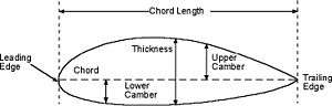
Broadly, an aerofoil is said to have positive camber if, as is commonly the case, its upper surface (or in the case of a propeller or turbine blade its forward surface) is the more convex. But camber is a complex property, that can be more fully characterized by an aerofoil's camber line, the curve Z(x) that is halfway between the upper and lower surfaces, and thickness function T(x), which describes the thickness of the aerofoil at any given point. Then, the upper and lower surfaces can be defined as follows:


Example – An aerofoil with reflexed camber line
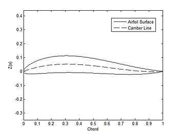
An aerofoil where the camber line curves back up near the trailing edge is called a reflexed camber aerofoil. Such an aerofoil is useful in certain situations, such as with tailless aircraft, because the moment about the aerodynamic center of the aerofoil can be 0. A camber line for such an aerofoil can be defined as follows (note that the lines over the variables indicates that they have been nondimensionalized by dividing through by the chord):
![\overline{Z}(x) = a\left[\left(b-1\right){\overline{x}}^3-b{\overline{x}}^2+\overline{x}\right]](../I/m/b5b8b40cb7ff70c9f22dd7acfc8a803bb25babe9.svg)
An aerofoil with a reflexed camber line is shown at right. The thickness distribution for a NACA 4-series aerofoil was used, with a 12% thickness ratio. The equation for this thickness distribution is:

Where t is the thickness ratio.
See also
References
- ↑ "U.S Centennial of Flight Commission". Archived from the original on 2008-09-20. Retrieved 2008-09-10.
Experiments that he began to carry out in 1804 allowed him to learn more about aerodynamics and wing structures using a whirling arm device. Cayley observed that birds soared long distances by simply twisting their arched wing surfaces and deduced that fixed-wing machines would fly if the wings were cambered. This was the first scientific testing of aerofoils as the part of the aircraft that is designed to produce lift.
- Sources
- Desktop Aerodynamics Digital Textbook. Retrieved 9/7/08.
- Theory of Wing Sections, Ira H.Abbott and Albert E.Von Doenhoff (Dover Publications-1959) ISBN 0-486-60586-8