CCFL inverter
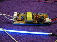
A CCFL inverter is an electrical inverter that supplies alternating current power to a cold cathode fluorescent lamp (CCFL). CCFLs are often used as inexpensive light units in electrical devices that are powered by direct current sources such as batteries. CCFL inverters are small, have switchover efficiency over 80%, and offer adjustable output of light. They are widely used for backlights for LCDs, or for rear lighting in advertising signs.
History


As for the inverter circuit of a cold cathode fluorescent lamp, a resonance type circuit has been widely used. This is sometimes referred to as the "Royer circuit".[1] However the proper definition of the Royer circuit requires that the inversion of a switching operation be performed in a state in which the transformer is saturated. An inverter circuit which performs the inversion operation by utilizing resonance in the collector circuit of a transistor is preferably referred to as the "collector resonance type circuit" or the "collector resonance type Royer circuit" in distinction from a true Royer circuit.[2] The multilevel inverters are basically classified into three topologies namely, the flying capacitor inverter, the diode clamped inverter and the cascaded H-bridge inverter. All the topologies have same property of reducing the harmonics. The cascaded has the disadvantage to need separate DC sources but circuit layout is compact and voltage sharing problem is absent.
The early designs of an inverter circuit for a cold cathode fluorescent lamp did not utilize the resonance method of a secondary circuit at all. Instead the so-called closed magnetic circuit type transformer having a small leakage inductance was used as a step-up transformer. The leakage inductance was such that it reduced the output voltage on the secondary side of the transformer. Since this was not desirable, it had to be made as small as possible.
Because the resonant frequency of the secondary side circuit of the transformer in the early designs was decided to have no relation with the operating frequency of the inverter circuit, the resonant frequency was set to a much higher frequency than that of the inverter circuit. This greatly reduces the influence of the inverter circuit on the operating frequency. A ballast capacitor Cb is essential for stabilization of the lamp current.
Another design for the inverter circuit of a cold cathode fluorescent lamp is shown in the figure of the “CCFL Inverter circuit of the past generation of technology“. It isn't used any more.
The more recent inverter circuit was invented by Hitachi electronics in Japan. It has come into world wide use as the so-called three-times or third harmonic resonance circuit, shown in the figure as the “advanced technology“. The resonance frequency of the secondary side circuit is three times that of the primary side. A step-up transformer with a greater short-circuit inductance value is suitable for use in this case.
The transformer which is actually used in the so-called three-times resonance circuit has a flat shape. Although the magnetic path structure is closed, the leakage of the magnetic flux is considerably more than that of the conventional type. The transformer therefore has a larger short circuit inductance value. The design (refer to figure of the “past generation of technology“) is such that the short circuit inductance value of the step-up transformer is increased to some degree, whereby a resonance circuit is created by the short circuit inductance (Lsc in the figures) and a capacitance component obtained on the secondary side of the step-up transformer. The resonance frequency of the circuit is set to a frequency three times as high as the operating frequency of the inverter circuit in order to generate a third-order harmonic in the secondary side circuit. The lamp current waveform has a trapezoid shape. The ballast capacitor Crb also functions as a resonance capacitor. As a result the conversion efficiency of the inverter circuit is considerably improved, and the step-up transformer is further miniaturized.
In the most recent circuit design shown, both the primary and secondary sides of the circuit operate at close to the same fundamental frequency. This began to be widely implemented in about 1996, and has greatly contributed to the miniaturization and higher efficiency of the inverter circuit used in a notebook type personal computer.

The short circuit inductance value of the step-up transformer is further increased from that of the three-times resonance design. The capacitance component of the secondary side circuit is also increased.
The next generation's inverter technology for the CCFL Lighting is the current resonance type inverter circuit. The resonance current which causes at the secondary side of the transformer is directly switching the primary side of the transformer through the switching transistor. It simplifies the circuit and improves efficiency.
See also
External links
- Notebook Inverter Schematic
- Jim Williams, "A fourth generation of LCD backlight technology: Component and measurement improvements refine performance", Linear Technology Application Note 65, November 1995.
- Descriptions of the Current-mode resonant inverter circuit for discharge lamp for the CCFL lighting.
References
- ↑ Royer Oscillator Circuit United States Patent 2783384
- ↑ P.J. Baxandall, "Transistor Sine-Wave LC Oscillators", International Convention on Transistors and Associated Semiconductor Devices, 25 May 1959, fig 5, p. 751