Line code

In telecommunication, a line code is a pattern of voltage, current, or photons used to represent digital data transmitted down a transmission line. This repertoire of signals is usually called a constrained code in data storage systems. Some signals are more prone to error than others when conveyed over a communication channel as the physics of the communication or storage medium constrains the repertoire of signals that can be used reliably.[1]
Common line encodings are unipolar, polar, bipolar, and Manchester code.
Transmission and storage
After line coding, the signal is put through a physical communication channel, either a transmission medium or data storage medium.[2][3] The most common physical channels are:
- the line-coded signal can directly be put on a transmission line, in the form of variations of the voltage or current (often using differential signaling).
- the line-coded signal (the "baseband signal") undergoes further pulse shaping (to reduce its frequency bandwidth) and then modulated (to shift its frequency) to create an "RF signal" that can be sent through free space.
- the line-coded signal can be used to turn on and off a light source in free-space optical communication, most commonly used in an infrared remote control.
- the line-coded signal can be printed on paper to create a bar code.
- the line-coded signal can be converted to magnetized spots on a hard drive or tape drive.
- the line-coded signal can be converted to pits on an optical disc.
Some of the more common binary line codes include:
| Signal | Comments | |
|---|---|---|
| NRZ–L | Non return to zero level. This is the standard positive logic signal format used in digital circuits. 1 forces a high level | |
| NRZ–M | Non return to zero mark 1 forces a transition | |
| NRZ–S | Non return to zero space 1 does nothing (keeps sending the previous level) | |
| RZ | Return to zero 1 goes high for half the bit period and returns to low | |
| Biphase–L | Manchester. Two consecutive bits of the same type force a transition at the beginning of a bit period. 1 forces a negative transition in the middle of the bit | |
| Biphase–M | Variant of Differential Manchester. There is always a transition halfway between the conditioned transitions. 1 forces a transition | |
| Biphase–S | Differential Manchester used in Token Ring. There is always a transition halfway between the conditioned transitions. 1 keeps level constant | |
| Differential Manchester (Alternative) | Need a Clock, always a transition in the middle of the clock period 1 is represented by no transition. |
|
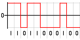
| Bipolar | The positive and negative pulses alternate. 1 forces a positive or negative pulse for half the bit period |

Each line code has advantages and disadvantages. The particular line code used is chosen to meet one or more of the following criteria:
- Minimize transmission hardware
- Facilitate synchronization
- Ease error detection and correction
- Minimize spectral content
- Eliminate a DC component
Disparity
The disparity of a bit pattern is the difference in the number of one bits vs the number of zero bits. The running disparity is the running total of the disparity of all previously transmitted words.[4]
Unfortunately, most long-distance communication channels cannot reliably transport a DC component. The DC component is also called the disparity, the bias, or the DC coefficient. The simplest possible line code, unipolar, gives too many errors on such systems, because it has an unbounded DC component.
Most line codes eliminate the DC component – such codes are called DC-balanced, zero-DC, or DC-free. There are three ways of eliminating the DC component:
- Use a constant-weight code. In other words, each transmitted code word is corrected such that every code word that contains some positive or negative levels also contains enough of the opposite levels, such that the average level over each code word is zero. For example, Manchester code and Interleaved 2 of 5.
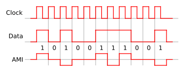
- Use a paired disparity code. In other words, the transmitter has to make sure that every code word that averages to a negative level is paired with another code word that averages to a positive level. Therefore, it must keep track of the running DC buildup, and always pick the code word that pushes the DC level back towards zero. The receiver is designed so that either code word of the pair decodes to the same data bits. For example, AMI, 8B10B, 4B3T, etc.
- Use a scrambler. For example, the scrambler specified in RFC 2615 for 64b/66b encoding.
Polarity
Bipolar line codes have two polarities, are generally implemented as RZ, and have a radix of three since there are three distinct output levels. One of the principle advantages of this type of code is that it can completely eliminate any DC component. This is important if the signal must pass through a transformer or a long transmission line.
Unfortunately, several long-distance communication channels have polarity ambiguity. To compensate, several people have designed polarity-insensitive transmission systems.[5][6][7][8] There are three ways of providing unambiguous reception of "0" bits or "1" bits over such channels:
- Pair each code word with the polarity-inverse of that code word. The receiver is designed so that either code word of the pair decodes to the same data bits, such as alternate mark inversion, Differential Manchester encoding, coded mark inversion, Miller encoding, etc.
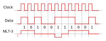
- differential coding each symbol relative to the previous symbol, such as MLT-3 encoding, NRZI, etc.
- invert the whole stream when inverted syncwords are detected
Run-length limited codes
For reliable clock recovery at the receiver, a maximum run length constraint may be imposed on the generated channel sequence, i.e., the maximum number of consecutive ones or zeros is bounded to a reasonable number. A clock period is recovered by observing transitions in the received sequence, so that a maximum run length guarantees such clock recovery, while sequences without such a constraint could seriously hamper the detection quality.
Run-length limited[9] or RLL coding is a line coding technique that is used to send arbitrary data over a communications channel with bandwidth limits. RLL codes are defined by four main parameters: m, n, d, k. The first two, m/n, refer to the rate of the code, while the remaining two specify the minimal d and maximal k number of zeroes between consecutive ones. This is used in both telecommunication and storage systems that move a medium past a fixed recording head.
Specifically, RLL bounds the length of stretches (runs) of repeated bits during which the signal does not change. If the runs are too long, clock recovery is difficult; if they are too short, the high frequencies might be attenuated by the communications channel. By modulating the data, RLL reduces the timing uncertainty in decoding the stored data, which would lead to the possible erroneous insertion or removal of bits when reading the data back. This mechanism ensures that the boundaries between bits can always be accurately found (preventing bit slip), while efficiently using the media to reliably store the maximal amount of data in a given space.
Early disk drives used very simple encoding schemes, such as RLL (0,1) FM code, followed by RLL (1,3) MFM code which were widely used in hard disk drives until the mid-1980s and are still used in digital optical discs such as CD, DVD, MD, Hi-MD and Blu-ray using EFM and EFMPLus[10] codes. Higher density RLL (2,7) and RLL (1,7) codes became the de facto industry standard for hard disks by the early 1990s.
Synchronization
Line coding should make it possible for the receiver to synchronize itself to the phase of the received signal. If the synchronization is not ideal, then the signal to be decoded will not have optimal differences (in amplitude) between the various digits or symbols used in the line code. This will increase the error probability in the received data.
Biphase line codes require at least one transition per bit time. This makes it easier to synchronize the transceivers and detect errors, however, the baud rate is greater than that of NRZ codes.
Other considerations
It is also preferred for the line code to have a structure that will enable error detection. Note that the line-coded signal and a signal produced at a terminal may differ, thus requiring translation.
A line code will typically reflect technical requirements of the transmission medium, such as optical fiber or shielded twisted pair. These requirements are unique for each medium, because each one has different behavior related to interference, distortion, capacitance and loss of amplitude.
Common line codes
- AMI
- Modified AMI codes: B8ZS, B6ZS, B3ZS, HDB3
- 2B1Q
- 4B5B
- 4B3T
- 6b/8b encoding
- Hamming Code
- 8b/10b encoding
- 64b/66b encoding
- 128b/130b encoding
- Coded mark inversion (CMI)
- Conditioned Diphase
- Eight-to-Fourteen Modulation (EFM), used in Compact Discs
- EFMPlus, used in DVDs
- RZ – Return-to-zero
- NRZ – Non-return-to-zero
- NRZI – Non-return-to-zero, inverted
- Manchester code, with its variants Differential Manchester and Biphase mark code
- pulse-position modulation, a generalization of Manchester code
- Miller encoding, also known as Delay encoding or Modified Frequency Modulation, with Modified Miller encoding as a variant
- MLT-3 Encoding
- Hybrid Ternary Codes
- Surround by complement (SBC)
- TC-PAM
Optical line codes:
See also
- Channel coding
- Source coding
- Modulation
- Physical layer
- Self-synchronizing code and bit synchronization
References
- ↑ K. Schouhamer Immink (2001). "A Survey of Codes for Optical Disk Recording". IEEE Journal on Selected Areas of Communications. 19: 751–764. Retrieved 2018-02-05.
- ↑ Karl Paulsen. "Coding for Magnetic Storage Mediums".2007.
- ↑ Abdullatif Glass; Nidhal Abdulaziz; and Eesa Bastaki (2007), "Slope line coding for telecommunication networks", IEEE International Conference on Signal Processing and Communication, Dubai: IEEE: 1537,
Line codes ... facilitates the transmission of data over telecommunication and computer networks and its storage in multimedia systems.
- ↑ Jens Kröger. "Data Transmission at High Rates via Kapton Flexprints for the Mu3e Experiment". 2014. p. 16
- ↑ Peter E. K. Chow. "Code converter for polarity-insensitive transmission systems". 1983.
- ↑ David A. Glanzer, Fieldbus Foundation. "Fieldbus Application Guide ... Wiring and Installation". Section "4.7 Polarity". p. 10
- ↑ George C. Clark Jr., and J. Bibb Cain. "Error-Correction Coding for Digital Communications". 2013. p. 255. quote: "When PSK data modulation is used, the potential exists for an ambiguity in the polarity of the received channel symbols. This problem can be solved in one of two ways. First ... a so-called transparent code. ..."
- ↑ Prakash C. Gupta. "Data Communications and Computer Networks". 2013. p. 13. quote: "Another benefit of differential encoding is its insensitivity to polarity of the signal. ... If the leads of a twisted pair are accidentally reversed..."
- ↑ Kees Schouhamer Immink (December 1990). "Runlength-Limited Sequences" (PDF). Proceedings of the IEEE. 78 (11): 1745–1759.
A detailed description is furnished of the limiting properties of runlength limited sequences.
- ↑ Kees Schouhamer Immink (1995). "EFMPlus: The Coding Format of the MultiMedia Compact Disc". IEEE Trans. on Consumer Electronics. CE-41: 491–497.
A high-density alternative to EFM is described.

External links
Line coding (digital baseband transmission) | ||
|---|---|---|
| Main articles | 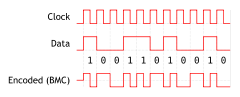 | |
| Basic line codes | ||
| Extended line codes | ||
| Optical line codes | ||
| ||