2D Primitives
All 2D primitives can be transformed with 3D transformations. Usually used as part of a 3D extrusion. Although infinitely thin, they are rendered with a 1 thickness.
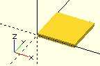
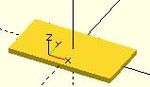
square
Creates a square or rectangle in the first quadrant. When center is true the square is centered on the origin. Argument names are optional if given in the order shown here.
square(size = [x, y], center = true/false);
square(size =  x    , center = true/false);
- parameters:
- size
- single value, square with both sides this length
- 2 value array [x,y], rectangle with dimensions x and y
- center
- false (default), 1st (positive) quadrant, one corner at (0,0)
- true, square is centered at (0,0)
- size
default values: square(); yields: square(size = [1, 1], center = false);
- examples:
equivalent scripts for this example
 square(size = 10);
 square(10);
 square([10,10]);
 .
 square(10,false);
 square([10,10],false);
 square([10,10],center=false);
 square(size = [10, 10], center = false);
 square(center = false,size = [10, 10] );
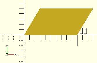
equivalent scripts for this example
 square([20,10],true);
 a=[20,10];square(a,true);
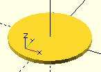
circle
Creates a circle at the origin. All parameters, except r, must be named.
circle(r=radius | d=diameter);
- Parameters
- r : circle radius. r name is the only one optional with circle.
- circle resolution is based on size, using $fa or $fs.
- r : circle radius. r name is the only one optional with circle.
- For a small, high resolution circle you can make a large circle, then scale it down, or you could set $fn or other special variables. Note: These examples exceed the resolution of a 3d printer as well as of the display screen.
scale([1/100, 1/100, 1/100]) circle(200); // create a high resolution circle with a radius of 2.
circle(2, $fn=50);                        // Another way.
- d : circle diameter (only available in versions later than 2014.03).
- $fa : minimum angle (in degrees) of each fragment.
- $fs : minimum circumferential length of each fragment.
- $fn : fixed number of fragments in 360 degrees. Values of 3 or more override $fa and $fs
- $fa, $fs and $fn must be named. click here for more details,.
defaults: circle(); yields: circle($fn = 0, $fa = 12, $fs = 2, r = 1);
equivalent scripts for this example
 circle(10);
 circle(r=10);
 circle(d=20);
 circle(d=2+9*2);
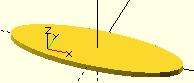
ellipse
An ellipse can be created from a circle by using either scale() or resize() to make the x and y dimensions unequal. See OpenSCAD User Manual/Transformations
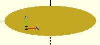
equivalent scripts for this example
 resize([30,10])circle(d=20);
 scale([1.5,.5])circle(d=20);
regular polygon
A regular polygon of 3 or more sides can be created by using circle() with $fn set to the number of sides. The following two pieces of code are equivalent.
circle(r=1, $fn=4);
 module regular_polygon(order = 4, r=1){
     angles=[ for (i = [0:order-1]) i*(360/order) ];
     coords=[ for (th=angles) [r*cos(th), r*sin(th)] ];
     polygon(coords);
 }
 regular_polygon();
These result in the following shapes, where the polygon is inscribed within the circle with all sides (and angles) equal. One corner points to the positive x direction. For irregular shapes see the polygon primitive below.
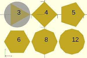
script for these examples
 translate([-42,  0]){circle(20,$fn=3);%circle(20,$fn=90);}
 translate([  0,  0]) circle(20,$fn=4);
 translate([ 42,  0]) circle(20,$fn=5);
 translate([-42,-42]) circle(20,$fn=6);
 translate([  0,-42]) circle(20,$fn=8);
 translate([ 42,-42]) circle(20,$fn=12);
 color("black"){
     translate([-42,  0,1])text("3",7,,center);
     translate([  0,  0,1])text("4",7,,center);
     translate([ 42,  0,1])text("5",7,,center);
     translate([-42,-42,1])text("6",7,,center);
     translate([  0,-42,1])text("8",7,,center);
     translate([ 42,-42,1])text("12",7,,center);
 }
polygon
Creates a multiple sided shape from a list of x,y coordinates. A polygon is the most powerful 2D object. It can create anything that circle and squares can, as well as much more. This includes irregular shapes with both concave and convex edges. In addition it can place holes within that shape.
polygon(points = [ [x, y], ... ], paths = [ [p1, p2, p3..], ...], convexity = N);
Parameters
- points
- The list of x,y points of the polygon. : A vector of 2 element vectors.
- Note: points are indexed from 0 to n-1.
- paths
- default
- If no path is specified, all points are used in the order listed.
- single vector
- The order to traverse the points. Uses indices from 0 to n-1. May be in a different order and use all or part, of the points listed.
- multiple vectors
- Creates primary and secondary shapes. Secondary shapes are subtracted from the primary shape (like difference). Secondary shapes may be wholly or partially within the primary shape.
- default
- A closed shape is created by returning from the last point specified to the first.
- convexity
- Integer number of "inward" curves, ie. expected path crossings of an arbitrary line through the polygon. See below.
defaults: polygon(); yields: polygon(points = undef, paths = undef, convexity = 1);
Example no holes
equivalent scripts for this example
 polygon(points=[[0,0],[100,0],[130,50],[30,50]]);
 polygon([[0,0],[100,0],[130,50],[30,50]], paths=[[0,1,2,3]]);
 polygon([[0,0],[100,0],[130,50],[30,50]],[[3,2,1,0]]);
 polygon([[0,0],[100,0],[130,50],[30,50]],[[1,0,3,2]]);

 a=[[0,0],[100,0],[130,50],[30,50]];
 b=[[3,0,1,2]];
 polygon(a);
 polygon(a,b);
 polygon(a,[[2,3,0,1,2]]);
Example one hole
equivalent scripts for this example
 polygon(points=[[0,0],[100,0],[0,100],[10,10],[80,10],[10,80]], paths=[[0,1,2],[3,4,5]],convexity=10);

 triangle_points =[[0,0],[100,0],[0,100],[10,10],[80,10],[10,80]];
 triangle_paths =[[0,1,2],[3,4,5]];
 polygon(triangle_points,triangle_paths,10);
The 1st path vector, [0,1,2], selects the points, [0,0],[100,0],[0,100], for the primary shape.
The 2nd path vector, [3,4,5], selects the points, [10,10],[80,10],[10,80], for the secondary shape.
The secondary shape is subtracted from the primary ( think difference() ).
Since the secondary is wholly within the primary, it leaves a shape with a hole.
Example multi hole
[Note: Requires version 2015.03] (for use of concat())
      //example polygon with multiple holes
a0 = [[0,0],[100,0],[130,50],[30,50]];     // main
b0 = [1,0,3,2];
a1 = [[20,20],[40,20],[30,30]];            // hole 1
b1 = [4,5,6];
a2 = [[50,20],[60,20],[40,30]];            // hole 2
b2 = [7,8,9];
a3 = [[65,10],[80,10],[80,40],[65,40]];    // hole 3
b3 = [10,11,12,13];
a4 = [[98,10],[115,40],[85,40],[85,10]];   // hole 4
b4 = [14,15,16,17];
a  = concat (a0,a1,a2,a3,a4);
b  = [b0,b1,b2,b3,b4];
polygon(a,b);
      //alternate
polygon(a,[b0,b1,b2,b3,b4]);
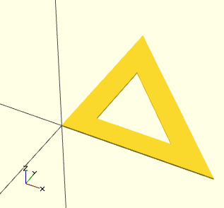
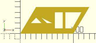
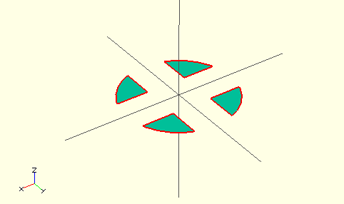
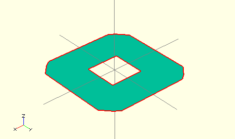
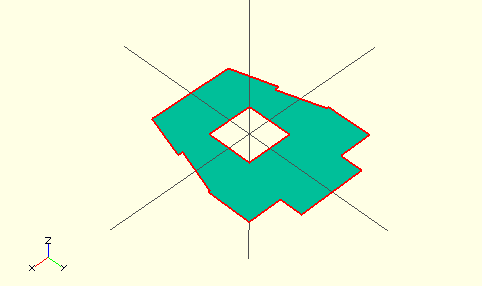
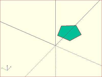
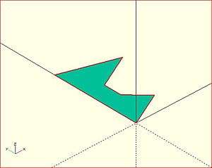
convexity
The convexity parameter specifies the maximum number of front sides (back sides) a ray intersecting the object might penetrate. This parameter is only needed for correctly displaying the object in OpenCSG preview mode and has no effect on the polyhedron rendering.
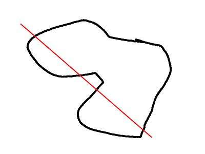
This image shows a 2D shape with a convexity of 4, as the ray indicated in red crosses the 2D shape a maximum of 4 times. The convexity of a 3D shape would be determined in a similar way. Setting it to 10 should work fine for most cases.
import_dxf
[Deprecated: import_dxf() will be removed in future releases. Use import() instead.]
Read a DXF file and create a 2D shape.
Example
linear_extrude(height = 5, center = true, convexity = 10)
		import_dxf(file = "example009.dxf", layer = "plate");
Text
The text module creates text as a 2D geometric object,
using fonts installed on the local system or provided as separate font file.
[Note: Requires version 2015.03]
Parameters
- text
- String. The text to generate.
- size
- Decimal. The generated text will have approximately an ascent of the given value (height above the baseline). Default is 10.
Note that specific fonts will vary somewhat and may not fill the size specified exactly, usually slightly smaller.
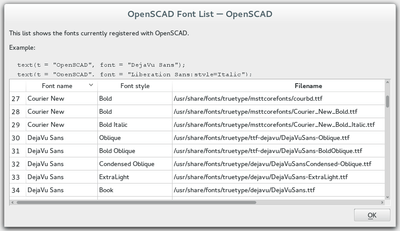
- font
- String. The name of the font that should be used. This is not the name of the font file, but the logical font name (internally handled by the fontconfig library). This can also include a style parameter, see below. A list of installed fonts & styles can be obtained using the font list dialog (Help -> Font List).
- halign
- String. The horizontal alignment for the text. Possible values are "left", "center" and "right". Default is "left".
- valign
- String. The vertical alignment for the text. Possible values are "top", "center", "baseline" and "bottom". Default is "baseline".
- spacing
- Decimal. Factor to increase/decrease the character spacing. The default value of 1 will result in the normal spacing for the font, giving a value greater than 1 will cause the letters to be spaced further apart.
- direction
- String. Direction of the text flow. Possible values are "ltr" (left-to-right), "rtl" (right-to-left), "ttb" (top-to-bottom) and "btt" (bottom-to-top). Default is "ltr".
- language
- String. The language of the text. Default is "en".
- script
- String. The script of the text. Default is "latin".
- $fn
- used for subdividing the curved path segments provided by freetype
Example
_example.png)
text("OpenSCAD");
- Note
To allow specification of particular Unicode characters you can specify them in a string with the following escape codes;
\x03 - single hex character (only allowed values are 01h - 7fh)
\u0123 - unicode char with 4 hexadecimal digits (note: Lowercase)
\U012345 - unicode char with 6 hexadecimal digits (note: Uppercase)
Example
t="\u20AC10 \u263A"; // 10 euro and a smilie
Using Fonts & Styles
Fonts are specified by their logical font name; in addition a style parameter can be added to select a specific font style like "bold" or "italic", such as:
font="Liberation Sans:style=Bold Italic"
The font list dialog (available under Help > Font List) shows the font name and the font style for each available font. For reference, the dialog also displays the location of the font file. You can drag a font in the font list, into the editor window to use in the text() statement.
OpenSCAD includes the fonts Liberation Mono, Liberation Sans, Liberation Sans Narrow and Liberation Serif. Hence, as fonts in general differ by platform type, use of these included fonts is likely to be portable across platforms.
For common/casual text usage, the specification of one of these fonts is recommended for this reason. Liberation Sans is the default font to encourage this.
In addition to the installed fonts, it's possible to add project specific font files. Supported font file formats are TrueType Fonts (*.ttf) and OpenType Fonts (*.otf). The files need to be registered with use<>.
use <ttf/paratype-serif/PTF55F.ttf>
After the registration, the font will also be listed in the font list dialog, so in case logical name of a font is unknown, it can be looked up there are it was registered.
OpenSCAD uses fontconfig to find and manage fonts, so it's possible to list the system configured fonts on command line using the fontconfig tools in a format similar to the GUI dialog.
$ fc-list -f "%-60{{%{family[0]}%{:style[0]=}}}%{file}\n" | sort

...
Liberation Mono:style=Bold Italic /usr/share/fonts/truetype/liberation2/LiberationMono-BoldItalic.ttf
Liberation Mono:style=Bold        /usr/share/fonts/truetype/liberation2/LiberationMono-Bold.ttf
Liberation Mono:style=Italic      /usr/share/fonts/truetype/liberation2/LiberationMono-Italic.ttf
Liberation Mono:style=Regular     /usr/share/fonts/truetype/liberation2/LiberationMono-Regular.ttf
...
Example
_font_style_example.png)
 square(10);

 translate([15, 15]) {
   text("OpenSCAD", font = "Liberation Sans");
 }

 translate([15, 0]) {
   text("OpenSCAD", font = "Liberation Sans:style=Bold Italic");
 }
Alignment
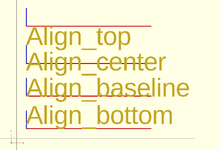
Vertical alignment
- top
- The text is aligned with the top of the bounding box at the given Y coordinate.
- center
- The text is aligned with the center of the bounding box at the given Y coordinate.
- baseline
- The text is aligned with the font baseline at the given Y coordinate. This is the default.
- bottom
- The text is aligned with the bottom of the bounding box at the given Y coordinate.
 text = "Align";
 font = "Liberation Sans";

 valign = [
   [  0, "top"],
   [ 40, "center"],
   [ 75, "baseline"],
   [110, "bottom"]
 ];

 for (a = valign) {
   translate([10, 120 - a[0], 0]) {
     color("red") cube([135, 1, 0.1]);
     color("blue") cube([1, 20, 0.1]);
     linear_extrude(height = 0.5) {
       text(text = str(text,"_",a[1]), font = font, size = 20, valign = a[1]);
     }
   }
 }
Horizontal alignment
- left
- The text is aligned with the left side of the bounding box at the given X coordinate. This is the default.
- center
- The text is aligned with the center of the bounding box at the given X coordinate.
- right
- The text is aligned with the right of the bounding box at the given X coordinate.
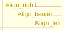
 text = "Align";
 font = "Liberation Sans";

 halign = [
   [10, "left"],
   [50, "center"],
   [90, "right"]
 ];

 for (a = halign) {
   translate([140, a[0], 0]) {
     color("red") cube([115, 2,0.1]);
     color("blue") cube([2, 20,0.1]);
     linear_extrude(height = 0.5) {
       text(text = str(text,"_",a[1]), font = font, size = 20, halign = a[1]);
     }
   }
 }
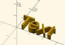
3D text
Text can be changed from a 2 dimensional object into a 3D object by using the linear_extrude function.
//3d Text Example
linear_extrude(4)
    text("Text");
3D to 2D Projection
Using the projection() function, you can create 2d drawings from 3d models, and export them to the dxf format. It works by projecting a 3D model to the (x,y) plane, with z at 0. If cut=true, only points with z=0 will be considered (effectively cutting the object), with cut=false(the default), points above and below the plane will be considered as well (creating a proper projection).
Example: Consider example002.scad, that comes with OpenSCAD.
Then you can do a 'cut' projection, which gives you the 'slice' of the x-y plane with z=0.
projection(cut = true) example002();
You can also do an 'ordinary' projection, which gives a sort of 'shadow' of the object onto the xy plane.
projection(cut = false) example002();
Another Example
You can also use projection to get a 'side view' of an object. Let's take example002, and move it up, out of the X-Y plane, and rotate it:
translate([0,0,25]) rotate([90,0,0]) example002();

Now we can get a side view with projection()
projection() translate([0,0,25]) rotate([90,0,0]) example002();
Links:
- example021.scad from Clifford Wolf's site.
- More complicated example from Giles Bathgate's blog
2D to 3D Extrusion
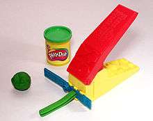
Extrusion is the process of creating an object with a fixed cross-sectional profile. OpenSCAD provides two commands to create 3D solids from a 2D shape: linear_extrude() and rotate_extrude(). Linear extrusion is similar to pushing Playdoh through a press with a die of a specific shape.
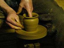
Rotational extrusion is similar to the process of turning or "throwing" a bowl on the Potter's wheel.
Both extrusion methods work on a (possibly disjointed) 2D shape which exists on the X-Y plane. While transformations that operates on both 2D shapes and 3D solids can move a shape off the X-Y plane, when the extrusion is performed the end result is not very intuitive. What actually happens is that any information in the third coordinate (the Z coordinate) is ignored for any 2D shape, this process amounts to an implicit projection() performed on any 2D shape before the extrusion is executed. It is recommended to perform extrusion on shapes that remains strictly on the X-Y plane.
Linear Extrude
Linear Extrusion is a operation that takes a 2D object as input and generates a 3D object as a result.
In OpenSCAD Extrusion is always performed on the projection (shadow) of the 2d object xy plane and along the Z axis; so if you rotate or apply other transformations to the 2d object before extrusion, it's shadow shape is what is extruded.
Although the extrusion is linear along the Z axis, a twist parameter is available that will cause the object to be rotated around the Z axis as it is extruding upward. This can be used to rotate the object at it's center, as if it is a spiral pillar, or produce a helical extrusion around the Z axis, like a pigs tail.
A scale parameter is also included so that the object can be expanded or contracted over the extent of the extrusion, allowing extrusions to be flared inward or outward.
Usage
linear_extrude(height = fanwidth, center = true, convexity = 10, twist = -fanrot, slices = 20, scale = 1.0, $fn = 16) {...}
You must use parameter names due to a backward compatibility issue.
height must be positive.
$fn is optional and specifies the resolution of the linear_extrude (higher number brings more "smoothness", but more computation time is needed).
If the extrusion fails for a non-trivial 2D shape, try setting the convexity parameter (the default is not 10, but 10 is a "good" value to try). See explanation further down.
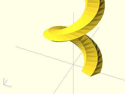
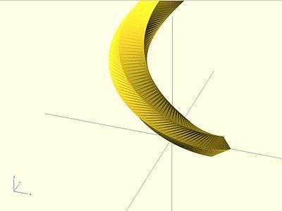
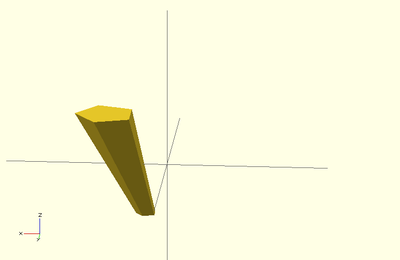
Twist
Twist is the number of degrees of through which the shape is extruded. Setting the parameter twist = 360 will extrude through one revolution. The twist direction follows the left hand rule.
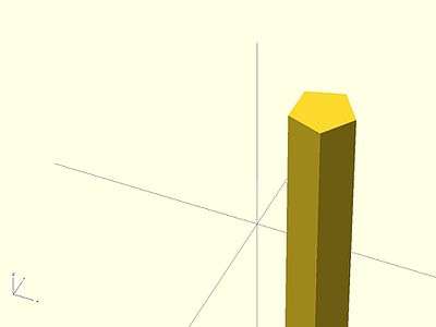
0° of Twist
linear_extrude(height = 10, center = true, convexity = 10, twist = 0)
translate([2, 0, 0])
circle(r = 1);
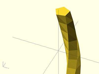
-100° of Twist
linear_extrude(height = 10, center = true, convexity = 10, twist = -100)
translate([2, 0, 0])
circle(r = 1);
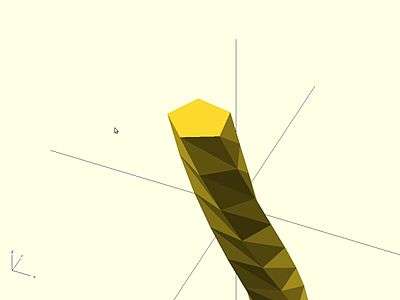
100° of Twist
linear_extrude(height = 10, center = true, convexity = 10, twist = 100)
translate([2, 0, 0])
circle(r = 1);
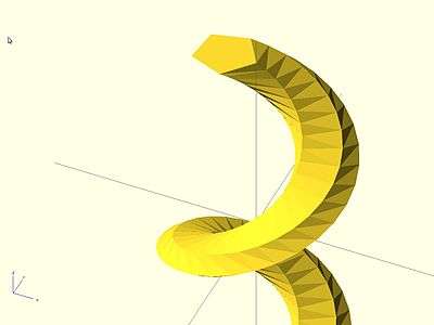
-500° of Twist
linear_extrude(height = 10, center = true, convexity = 10, twist = -500)
translate([2, 0, 0])
circle(r = 1);
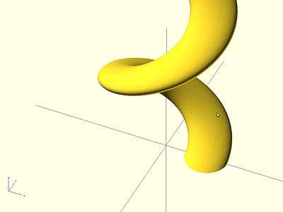
Center
It is similar to the parameter center of cylinders. If center is false the linear extrusion Z range is from 0 to height; if it is true, the range is from -height/2 to height/2.
center = true
linear_extrude(height = 10, center = true, convexity = 10, twist = -500)
translate([2, 0, 0])
circle(r = 1);
center = false
linear_extrude(height = 10, center = false, convexity = 10, twist = -500)
translate([2, 0, 0])
circle(r = 1);
Mesh Refinement
The slices parameter defines the number of intermediate points along the Z axis of the extrusion. Its default increases with the value of twist. Explicitly setting slices may improve the output refinement.
linear_extrude(height = 10, center = false, convexity = 10, twist = 360, slices = 100)
translate([2, 0, 0])
circle(r = 1);
The special variables $fn, $fs and $fa can also be used to improve the output. If slices is not defined, its value is taken from the defined $fn value.
linear_extrude(height = 10, center = false, convexity = 10, twist = 360, $fn = 100)
translate([2, 0, 0])
circle(r = 1);
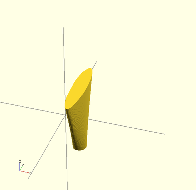
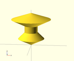
Scale
Scales the 2D shape by this value over the height of the extrusion. Scale can be a scalar or a vector:
 linear_extrude(height = 10, center = true, convexity = 10, scale=3)
 translate([2, 0, 0])
 circle(r = 1);
 linear_extrude(height = 10, center = true, convexity = 10, scale=[1,5], $fn=100)
 translate([2, 0, 0])
 circle(r = 1);
Note that if scale is a vector, the resulting side walls may be nonplanar. Use twist=0 and the slices parameter to avoid asymmetry.
 linear_extrude(height=10, scale=[1,0.1], slices=20, twist=0)
 polygon(points=[[0,0],[20,10],[20,-10]]);
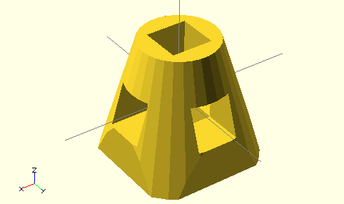
Rotate Extrude
Rotational extrusion spins a 2D shape around the Z-axis to form a solid which has rotational symmetry. One way to think of this operation is to imagine a Potter's wheel placed on the X-Y plane with its axis of rotation pointing up towards +Z. Then place the to-be-made object on this virtual Potter's wheel (possibly extended down below the X-Y plane towards -Z, take the cross-section of this object on the X-Z plane but keep only the right half (X >= 0). That is the 2D shape that need to be fed to rotate_extrude() as the child in order to generate this solid.
Since a 2D shape is rendered by OpenSCAD on the X-Y plane, an alternative way to think of this operation is as follows: spins a 2D shape around the Y-axis to form a solid. The resultant solid is placed so that its axis of rotation lies along the Z-axis.
Just like the linear_extrude, the extrusion is always performed on the projection of the 2D polygon to the XY plane. Transformations like rotate, translate, etc. applied to the 2D polygon before extrusion will modify the projection of the 2D polygon to the XY plane and therefore will also modify the appearance of the final 3D object.
So a translation in Z of the 2D polygon will have no effect on the result (as also the projection is not affected). A translation in X increases the diameter of the final object. A translation in Y results in a shift of the final object in Z direction. A rotation about the X or Y axis will distort the cross section of the final object, as also the projection to the XY plane is distorted.
Don't get confused, as OpenSCAD renders 2D polygons with a certain height in the Z direction, so the 2D object (with it's height) apears to have a bigger projection to the XY plane. But for the projection to the XY plane and also for the later extrusion only the base polygon without height is used.
It can not be used to produce a helix or screw threads.
The 2D shape must lie completely on either the right (recommended) or the left side of the Y-axis. More precisely speaking, every vertex of the shape must have either x >= 0 or x <= 0. If the shape spans the X axis a warning will be shown in the console windows and the rotate_extrude() will be ignored. If the 2D shape touches the Y axis, i.e. at x=0, it must be a line that touches, not a point, as a point will result in a zero thickness 3D object, which is invalid; this will result in a CGAL error. For OpenSCAD versions prior to 2016.xxxx, if the shape is in the negative axis the faces will be inside-out, which may cause undesired effects.
Parameters
Usage
rotate_extrude(angle = 360, convexity = 2) {...}

You must use parameter names due to a backward compatibility issue.
- convexity
- If the extrusion fails for a non-trival 2D shape, try setting the convexity parameter (the default is not 10, but 10 is a "good" value to try). See explanation further down.
- angle [Note: Requires version 2019.05] : Defaults to 360. Specifies the number of degrees to sweep, starting at the positive X axis. The direction of the sweep follows the Right Hand Rule, hence a negative angle will sweep clockwise.
Examples
→
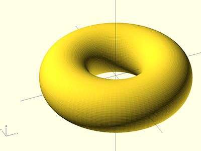
A simple torus can be constructed using a rotational extrude.
rotate_extrude(convexity = 10)
translate([2, 0, 0])
circle(r = 1);
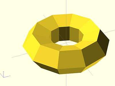
Mesh Refinement

→
Increasing the number of fragments that the 2D shape is composed of will improve the quality of the mesh, but take longer to render.
rotate_extrude(convexity = 10)
translate([2, 0, 0])
circle(r = 1, $fn = 100);
→
The number of fragments used by the extrusion can also be increased.
rotate_extrude(convexity = 10, $fn = 100)
translate([2, 0, 0])
circle(r = 1, $fn = 100);
Using the parameter angle (with OpenSCAD versions 2016.xx), a hook can be modeled .
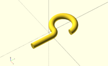
translate([0,60,0])
   rotate_extrude(angle=270, convexity=10)
       translate([40, 0]) circle(10);
rotate_extrude(angle=90, convexity=10)
   translate([20, 0]) circle(10);
translate([20,0,0])
   rotate([90,0,0]) cylinder(r=10,h=80);
Extruding a Polygon
Extrusion can also be performed on polygons with points chosen by the user.
Here is a simple polygon and its 200 step rotational extrusion. (Note it has been rotated 90 degrees to show how the rotation will look; the rotate_extrude() needs it flat).
rotate([90,0,0]) polygon( points=[[0,0],[2,1],[1,2],[1,3],[3,4],[0,5]] );
rotate_extrude($fn=200) polygon( points=[[0,0],[2,1],[1,2],[1,3],[3,4],[0,5]] );
→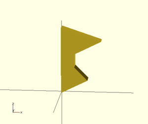
For more information on polygons, please see: 2D Primitives: Polygon.
Description of extrude parameters
Extrude parameters for all extrusion modes
| convexity | Integer. The convexity parameter specifies the maximum number of front sides (back sides) a ray intersecting the object might penetrate.
This parameter is only needed for correctly displaying the object in OpenCSG preview mode and has no effect on the polyhedron rendering. |
This image shows a 2D shape with a convexity of 4, as the ray indicated in red crosses the 2D shape a maximum of 4 times. The convexity of a 3D shape would be determined in a similar way. Setting it to 10 should work fine for most cases.
Extrude parameters for linear extrusion only
| height | The extrusion height |
| center | If true the solid will be centered after extrusion |
| twist | The extrusion twist in degrees |
| slices | Similar to special variable $fn without being passed down to the child 2D shape. |
| scale | Scales the 2D shape by this value over the height of the extrusion. |
DXF Extrusion
With the import() and extrusion modules it is possible to convert 2D objects read from DXF files to 3D objects. See also 2D to 3D Extrusion.
Linear Extrude
Example of linear extrusion of a 2D object imported from a DXF file.
linear_extrude(height = fanwidth, center = true, convexity = 10)
   import (file = "example009.dxf", layer = "fan_top");
Rotate Extrude
Example of rotational extrusion of a 2D object imported from a DXF file.
rotate_extrude(convexity = 10)
   import (file = "example009.dxf", layer = "fan_side", origin = fan_side_center);
Getting Inkscape to work
Inkscape is an open source drawing program. Tutorials for transferring 2d DXF drawings from Inkscape to OpenSCAD are available here:
- http://repraprip.blogspot.com/2011/05/inkscape-to-openscad-dxf-tutorial.html (Very simple, needs path segments to be straight lines)
- http://tonybuser.com/?tag=inkscape (More complicated, involves conversion to Postscript)
- http://bobcookdev.com/inkscape/inkscape-dxf.html (Better DXF Export, native support for bezier curves)
- http://www.bigbluesaw.com/saw/big-blue-saw-blog/general-updates/big-blue-saws-dxf-export-for-inkscape.html (even better support, works as of 10/29/2014, see link below registration window. Note: As of 6/17/15 only works with version 0.48.5 or earlier of inkscape, due to a breaking change made in 0.91.)
- http://www.instructables.com/id/Convert-any-2D-image-to-a-3D-object-using-OpenSCAD/ (Convert any 2D image to a 3D object using OpenSCAD)
- http://carrefour-numerique.cite-sciences.fr/fablab/wiki/doku.php?id=projets:de_inkscape_a_openscad (French, directly exports OpenSCAD file)