
We are students from Faculty of Computer systems and Control, Technical University of Sofia. Our 68 group is divided into two sub-groups; we constitute the first 68b one. Here are our names:
Aleksander Kovachev, Antoniya Tasheva, Hristo Savov, Jordan Slavov, Kalina Mineva, Kristina Miteva, Lora Kirilova, Maria Lambova, Miko Stefanov, Petjo Dimitrov, Petyr Chorbadjiiski, Silvia, Spasen Tsenov, Stilyan Savov, Svetoslav Tsonev, Tanya Kostadinova.
Lab 1: Investigating passive resistive circuits by Microlab
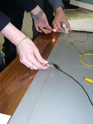
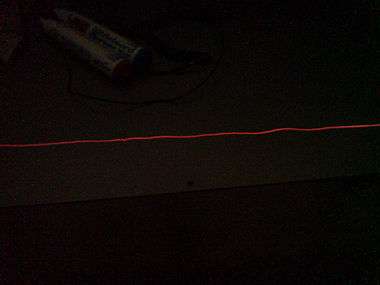
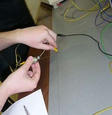
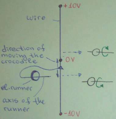
Lab 2: The genuine Ohm's experiment
Thursday, March 27, 2008, 16.45 h
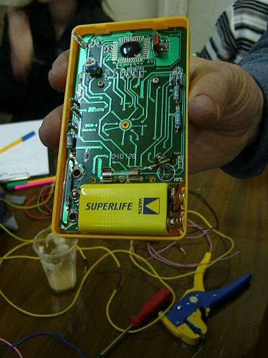
In the beginning, we had an "accident" with a $3 Chinese multimeter (VOM) - when we plugged its black test lead into the jack it just went down and "disappeared". Then we decided to take advantage of this opportunity and began applying a kind of reverse engineering to it:) Tell here what you have seen inside the multimeter...


Lab 3: "Inventing" a negative feedback BJT current source
Thursday, April 10, 2008, 16.45 h
Transistor as a current-stable resistor
Comparison with a voltage-stable resistor

Making transistor behave as a voltage-stable resistor
Building the simplest negative feedback follower
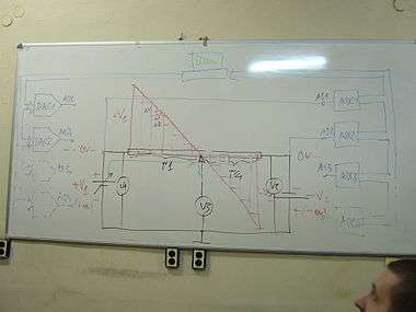
Building an emitter follower on the whiteboard

Mounting the emitter follower on the PCB
Investigating the emitter follower
Making transistor behave again as a current-stable resistor
Lab 4: How to make perfect components by parallel NFB
Is the real diode a perfect component?

A forward voltage drop VF appears across a real diode when a current flows through it... What is this voltage drop - useful or harmful? Sometimes it is useful; other times it is harmful...
"Useful" examples. When we make voltage stabilizers, we need this voltage drop. In these cases we do all that is possible to create and increase this useful voltage drop appearing across various diode component: diodes, LEDs, zeners, multiple diodes connected in series...
"Harmful" examples. In other cases, when we use a diode as a switching element, we do all that is possible to decrease and even to remove this harmful voltage drop... Then we need an ideal diode without forvard voltage drop VF...
Making the simplest parallel diode limiter

Why do we connect a reasistor R between the input voltage source and the diode (load)?
What does the combination (VIN + R) represent? What is it?
Making an "ideal" diode without VF
Deriving the basic idea from our human routine
(write here all the situations in your daily routine where you removed all the obstacles standing in your way:) Circuit-fantasist 06:36, 26 April 2008 (UTC)
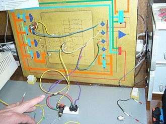
Implementing the powerful idea into an electrical circuit
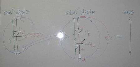
What have we actually done here? How does it operate? What is the final result?
The answer is amazing: we have made just... a piece of wire...?!? What do you think about this speculation? Is it always right? Circuit-fantasist (talk) 06:59, 26 April 2008 (UTC)
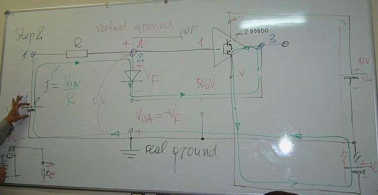
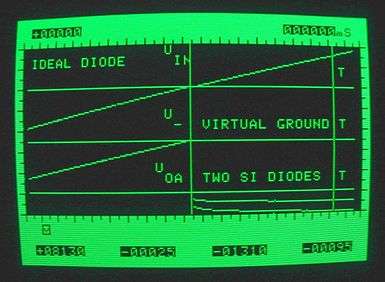
Making an almost ideal "op-amp" diode
An op-amp acting as a varying voltage source
What can act as a varying voltage source in our electronic circuit? What can "help" the imperfect diode by adding so much voltage as it loses across the diode? At last Lab 3 we were using transistors for such a purpose; let's now, for the sake of change, use an op-amp...
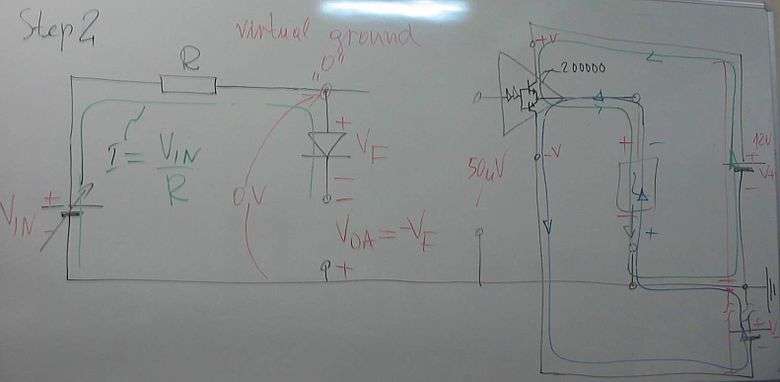
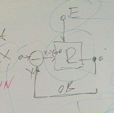
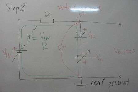
Now the op-amp has to "insert" the "helping" voltage VF into the circuit; so, how to connect it?
Finishing the op-amp circuit
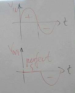
Eureka! We have invented an (almost) ideal diode without (any) forvard voltage VF!


Enlarging the powerful "helping" idea by destroying...
...multiple diode voltage drops...
...zener diode voltage drop...

...resistor voltage drop
With the same success we can destroy the "harmful" voltage drop across a resistor. What a circuit can we "invent" in this way? Write its name here....
Making the harmful voltage drop act as an input
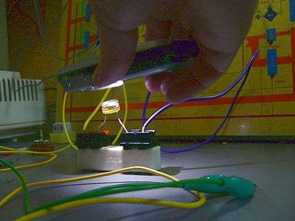
Here we have connected a photoresistor in the feedback loop...
Generalizing the powerful "helping" idea
We are already true magicians as we can transform any imperfect component into an almost ideal one! In this lab, we have transmuted a real diode (ordinary, LED, zener, any combinations of them, etc.), a resistor and a photoresistor into... a piece of wire:) having no any voltage drop across it! But with the same success we can make a "botomless" capacitor (an op-amp inverting integrator)... For this purpose, we just incorporate a varying battery to the imperfect component that compensated the losses inside the component. All the op-amp inverting circuits exploit this clever trick.
Resources
Op-amp circuit builder shows how to build various op-amp inverting circuits (an animated flash movie).
How do we create a virtual ground? is a circuit story about the great phenomenon.
Op-amp inverting current-to-voltage converter reveals the basic idea behind the famous circuit.
How do we build an op-amp ammeter? is a similar story about the active ammeter.
Lab 5: Investigating DAC and ADC
Thursday, May 8, 2008, 16.45 h
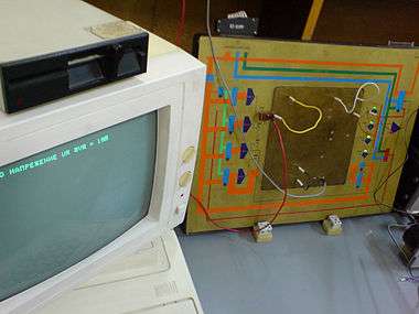


The pictures are made by Jordan Slavov.