Wadley loop
The Wadley loop circuit was designed by Dr. Trevor Wadley in the 1940s in South Africa and was first used for a stable Wavemeter.
Overview
In a traditional superheterodyne radio receiver, most oscillator drift and instability occurs in the first frequency converter stage, because it is tunable and operating at a high frequency. In theory, if one can eliminate this drift, the receiver will be stable.
Unlike other drift-reducing techniques (such as crystal control or frequency synthesis), the Wadley Loop does not attempt to stabilize the oscillator. Instead, it cancels the drift mathematically.
Principles of operation
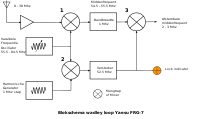
The Wadley loop works by:
- combining the first oscillator with the received signal in a frequency mixer to translate it to an intermediate frequency that is above the receiver's tuning range,
- mixing the same oscillator with a comb of harmonics from a crystal oscillator,
- selecting one of the results of (2) with a band-pass filter, and
- mixing this with the IF signal from (1).
Since the high-IF of part 1 drifts in the same direction, and the same amount, as the "synthetic oscillator" of part 3, when they are mixed in part 4 the drift terms cancel out and the result is a crystal-stable signal at a second intermediate frequency.
But the drift makes it impossible to use high-IF selectivity to reject undesired signals. Instead, the high IF is designed with a bandpass characteristic. Also, since the first oscillator is cancelled out, it cannot be used to tune a particular signal. Instead, it selects an entire band of signals - which one depends on which harmonic was chosen in part 3 above. The size of the band is equal to the spacing of the crystal harmonics. A conventionally tuned "back end" selects the desired signal from the band of signals presented at the second IF.
Example
Let say we want to pick up signals from 0 to 30 MHz. This is divided into 30 1 MHz bands, which are then translated to a band at 44-45 MHz. To convert 0-1 MHz, the first oscillator must be 45 MHz, to convert 1-2 MHz it must be 46 MHz, and so on. Meanwhile, the first oscillator is also mixed with harmonics from a 1 MHz crystal and put the result through a 42 MHz filter. Only one harmonic gets through. When the first oscillator is 45 MHz, it is the third harmonic, because 45 - 3 = 42. At 46 MHz, it is the fourth harmonic, and so on. The oscillator does not have to be exactly 45, 46, and so on, only close enough to get through the 42 MHz bandpass filter. Let's say it is 45.1 . Then we get 42.1 from the filter, and 45.1 - 42.1 is still 3. When the high IF is mixed with the 42 MHz, the result is a band of signals from 3 MHz to 2 MHz, from which the desired signal is selected, perhaps with a conventional superheterodyne back-end converting 3-2 MHz to 455 kHz and finally demodulating the signal back to audio. The overall receiver drift consists of the crystal's drift plus the 3 MHz back-end, so when we're listening to a 30 MHz signal, this receiver is about ten times as stable as one using a high-frequency tunable VFO.
To a new user, the feel of the first oscillator tuning control is counterintuitive. Although the knob moves in a continuous, analog fashion, its effect on receiver operation is discrete, that is, the tuning advances in 1 MHz jumps.
An example is Yaesu's FRG-7 communications receiver,[1] which uses the system to remove local oscillator drift. The Racal RA17 and Realistic DX-302[2] also used the Wadley Loop in their design.
An optical implementation of a Wadley Loop has recently been proposed. This allows a compact relatively unstable laser to be used as a local oscillator, with the system stability being obtained from a master 'comb source' (usually a pulsed laser, such as a mode-locked laser), possibly common to many receivers within an exchange.[3]
Notes
- Wadley Drift Cancelling Loop
- "DX-302 Owner's manual" (PDF). Retrieved 3 February 2018.
- https://www.osapublishing.org/oe/abstract.cfm?uri=oe-23-15-19891