Swim lane
A swimlane (or swimlane diagram) is used in process flow diagrams, or flowcharts, that visually distinguishes job sharing and responsibilities for sub-processes of a business process. Swimlanes may be arranged either horizontally or vertically.
Attributes of a swimlane
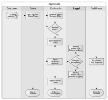
The swim lane flowchart differs from other flowcharts in that processes and decisions are grouped visually by placing them in lanes. Parallel lines divide the chart into lanes, with one lane for each person, group or sub process. Lanes are labelled to show how the chart is organized.
In the accompanying example, the vertical direction represents the sequence of events in the overall process, while the horizontal divisions depict what sub-process is performing that step. Arrows between the lanes represent how information or material is passed between the sub processes.
Alternately, the flow can be rotated so that the sequence reads horizontally from left to right, with the roles involved being shown at the left edge. This can be easier to read and design, since computer screens are typically wider than they are tall, which gives an improved view of the flow.
Use of standard symbols enables clear linkage to be shown between related flow charts when charting flows with complex relationships.
Usage
When used to diagram a business process that involves more than one department, swimlanes often serve to clarify not only the steps and who is responsible for each one, but also how delays, mistakes or cheating are most likely to occur.
Many process modeling methodologies utilize the concept of swim lanes, as a mechanism to organize activities into separate visual categories in order to illustrate different functional capabilities or responsibilities (organisational roles). Swim lanes are used in Business Process Modeling Notation (BPMN) and Unified Modeling Language activity diagram modeling methodologies.
Alternative terms
A Swimlane was first introduced to computer-based Process Modeling by iGrafx in 1993. It may also be referred to as a functional band (as it is in Microsoft Visio 2007) and is used in the same way, to create a cross functional flowchart to map a process within the functional units of a business.[1] The term functional band came after the use of swim lane and is seemingly in decline as the acceptable term as BPMN has been more widely accepted as a modeling standard.
Origin
Swimlane diagrams first appeared in the 1940s as a variation of the flow process chart called multi-column charts.[2] They were called Swim Lane diagrams by Geary Rummler and Alan Brache in their book Improving Performance (1990). They were first introduced to computer-based diagramming by iGrafx. Swimlanes are also known as "Rummler-Brache Diagrams". Another possible origin of the term swim lane is as part of the JBoss jBPM jPDL (Process Definition Language) graphical process designer a part of the JBoss jBPM framework for process languages.[3]
The SwimLane presentation was developed in the early 1980s by Prof. Dr.-Ing. Binner as part of his doctoral thesis on the requirements of the IT and CIM concept at the Institute for Factory Facilities at Prof. Wiendahl at TU-Har.
A process model was developed in which the role-based process analysis and modeling was the starting point for the IT-based IT solution or, in the case, the CIM solution with which the development of an IT-CIM concept was possible.
See also
References
External links
- Swim lane Guidelines, Agile Modeling, Process Mapping