Radio propagation
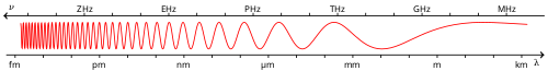
Radio propagation is the behavior of radio waves as they travel, or are propagated, from one point to another, or into various parts of the atmosphere.[1] As a form of electromagnetic radiation, like light waves, radio waves are affected by the phenomena of reflection, refraction, diffraction, absorption, polarization, and scattering.[2] Understanding the effects of varying conditions on radio propagation has many practical applications, from choosing frequencies for international shortwave broadcasters, to designing reliable mobile telephone systems, to radio navigation, to operation of radar systems.
| Part of a series on |
| Antennas |
|---|
 |
|
Common types |
|
Safety and regulation
|
|
Radiation sources / regions
|
Several different types of propagation are used in practical radio transmission systems. Line-of-sight propagation means radio waves which travel in a straight line from the transmitting antenna to the receiving antenna. Line of sight transmission is used to medium range radio transmission such as cell phones, cordless phones, walkie-talkies, wireless networks, FM radio and television broadcasting and radar, and satellite communication, such as satellite television. Line-of-sight transmission on the surface of the Earth is limited to the distance to the visual horizon, which depends on the height of transmitting and receiving antennas. It is the only propagation method possible at microwave frequencies and above. At microwave frequencies, moisture in the atmosphere (rain fade) can degrade transmission.
At lower frequencies in the MF, LF, and VLF bands, due to diffraction radio waves can bend over obstacles like hills, and travel beyond the horizon as surface waves which follow the contour of the Earth. These are called ground waves. AM broadcasting stations use ground waves to cover their listening areas. As the frequency gets lower, the attenuation with distance decreases, so very low frequency (VLF) and extremely low frequency (ELF) ground waves can be used to communicate worldwide. VLF and ELF waves can penetrate significant distances through water and earth, and these frequencies are used for mine communication and military communication with submerged submarines.
At medium wave and shortwave frequencies (MF and HF bands) radio waves can refract from a layer of charged particles (ions) high in the atmosphere, called the ionosphere. This means that radio waves transmitted at an angle into the sky can be reflected back to Earth beyond the horizon, at great distances, even transcontinental distances. This is called skywave propagation. It is used by amateur radio operators to talk to other countries, and shortwave broadcasting stations that broadcast internationally. Skywave communication is variable, dependent on conditions in the upper atmosphere; it is most reliable at night and in the winter. Due to its unreliability, since the advent of communication satellites in the 1960s, many long range communication needs that previously used skywaves now use satellites.
In addition, there are several less common radio propagation mechanisms, such as tropospheric scattering (troposcatter) and near vertical incidence skywave (NVIS) which are used in specialized communication systems.
Free space propagation
In free space, all electromagnetic waves (radio, light, X-rays, etc.) obey the inverse-square law which states that the power density of an electromagnetic wave is proportional to the inverse of the square of the distance from a point source[3] or:


At typical communication distances from a transmitter, the transmitting antenna usually can be approximated by a point source. Doubling the distance of a receiver from a transmitter means that the power density of the radiated wave at that new location is reduced to one-quarter of its previous value.
The power density per surface unit is proportional to the product of the electric and magnetic field strengths. Thus, doubling the propagation path distance from the transmitter reduces each of these received field strengths over a free-space path by one-half.
Radio waves in vacuum travel at the speed of light. The Earth's atmosphere is thin enough that radio waves in the atmosphere travel very close to the speed of light, but variations in density and temperature can cause some slight refraction (bending) of waves over distances.
Modes
At different frequencies, radio waves travel through the atmosphere by different mechanisms or modes:[4]
| Band | Frequency | Wavelength | Propagation via | |
|---|---|---|---|---|
| ELF | Extremely Low Frequency | 3–30 Hz | 100,000–10,000 km | Guided between the Earth and the D layer of the ionosphere. |
| SLF | Super Low Frequency | 30–300 Hz | 10,000–1,000 km | Guided between the Earth and the ionosphere. |
| ULF | Ultra Low Frequency | 0.3–3 kHz (300–3,000 Hz) | 1,000–100 km | Guided between the Earth and the ionosphere. |
| VLF | Very Low Frequency | 3–30 kHz (3,000–30,000 Hz) | 100–10 km | Guided between the Earth and the ionosphere. |
| LF | Low Frequency | 30–300 kHz (30,000–300,000 Hz) | 10–1 km | Guided between the Earth and the ionosphere. |
| MF | Medium Frequency | 300–3000 kHz (300,000–3,000,000 Hz) | 1000–100 m | Ground waves.
E, F layer ionospheric refraction at night, when D layer absorption weakens. |
| HF | High Frequency (Short Wave) | 3–30 MHz (3,000,000–30,000,000 Hz) | 100–10 m | E layer ionospheric refraction.
F1, F2 layer ionospheric refraction. |
| VHF | Very High Frequency | 30–300 MHz (30,000,000–300,000,000 Hz) | 10–1 m | Line-of-sight propagation.
Infrequent E ionospheric (Es) refraction. Uncommonly F2 layer ionospheric refraction during high sunspot activity up to 50 MHz and rarely to 80 MHz. Sometimes tropospheric ducting or meteor scatter |
| UHF | Ultra High Frequency | 300–3000 MHz (300,000,000–3,000,000,000 Hz) | 100–10 cm | Line-of-sight propagation. Sometimes tropospheric ducting. |
| SHF | Super High Frequency | 3–30 GHz (3,000,000,000–30,000,000,000 Hz) | 10–1 cm | Line-of-sight propagation. Sometimes rain scatter. |
| EHF | Extremely High Frequency | 30–300 GHz (30,000,000,000–300,000,000,000 Hz) | 10–1 mm | Line-of-sight propagation, limited by atmospheric absorption to a few kilometers |
| THF | Tremendously High frequency | 0.3–3 THz (300,000,000,000–3,000,000,000,000 Hz) | 1–0.1 mm | Line-of-sight propagation. |
Direct modes (line-of-sight)
Line-of-sight refers to radio waves which travel directly in a line from the transmitting antenna to the receiving antenna. It does not necessarily require a cleared sight path; at lower frequencies radio waves can pass through buildings, foliage and other obstructions. This is the most common propagation mode at VHF and above, and the only possible mode at microwave frequencies and above. On the surface of the Earth, line of sight propagation is limited by the visual horizon to about 40 miles (64 km). This is the method used by cell phones, cordless phones, walkie-talkies, wireless networks, point-to-point microwave radio relay links, FM and television broadcasting and radar. Satellite communication uses longer line-of-sight paths; for example home satellite dishes receive signals from communication satellites 22,000 miles (35,000 km) above the Earth, and ground stations can communicate with spacecraft billions of miles from Earth.
Ground plane reflection effects are an important factor in VHF line of sight propagation. The interference between the direct beam line-of-sight and the ground reflected beam often leads to an effective inverse-fourth-power (1/distance4) law for ground-plane limited radiation.
Surface modes (groundwave)
Lower frequency (between 30 and 3,000 kHz) vertically polarized radio waves can travel as surface waves following the contour of the Earth; this is called groundwave propagation.
In this mode the radio wave propagates by interacting with the conductive surface of the Earth. The wave "clings" to the surface and thus follows the curvature of the Earth, so groundwaves can travel over mountains and beyond the horizon. Ground waves propagate in vertical polarization so vertical antennas (monopoles) are required. Since the ground is not a perfect electrical conductor, ground waves are attenuated as they follow the Earth’s surface. Attenuation is proportional to frequency, so ground waves are the main mode of propagation at lower frequencies, in the MF, LF and VLF bands. Ground waves are used by radio broadcasting stations in the MF and LF bands, and for time signals and radio navigation systems.
At even lower frequencies, in the VLF to ELF bands, an Earth-ionosphere waveguide mechanism allows even longer range transmission. These frequencies are used for secure military communications. They can also penetrate to a significant depth into seawater, and so are used for one-way military communication to submerged submarines.
Early long distance radio communication (wireless telegraphy) before the mid-1920s used low frequencies in the longwave bands and relied exclusively on ground-wave propagation. Frequencies above 3 MHz were regarded as useless and were given to hobbyists (radio amateurs). The discovery around 1920 of the ionospheric reflection or skywave mechanism made the medium wave and short wave frequencies useful for long distance communication and they were allocated to commercial and military users.[5]
Ionospheric modes (skywave)
Skywave propagation, also referred to as skip, is any of the modes that rely on reflection and refraction of radio waves from the ionosphere. The ionosphere is a region of the atmosphere from about 60 to 500 km (37 to 311 mi) that contains layers of charged particles (ions) which can refract a radio wave back toward the Earth. A radio wave directed at an angle into the sky can be reflected back to Earth beyond the horizon by these layers, allowing long distance radio transmission. The F2 layer is the most important ionospheric layer for long-distance, multiple-hop HF propagation, though F1, E, and D-layers also play significant roles. The D-layer, when present during sunlight periods, causes significant amount of signal loss, as does the E-layer whose maximum usable frequency can rise to 4 MHz and above and thus block higher frequency signals from reaching the F2-layer. The layers, or more appropriately "regions", are directly affected by the sun on a daily diurnal cycle, a seasonal cycle and the 11-year sunspot cycle and determine the utility of these modes. During solar maxima, or sunspot highs and peaks, the whole HF range up to 30 MHz can be used usually around the clock and F2 propagation up to 50 MHz is observed frequently depending upon daily solar flux 10.7cm radiation values. During solar minima, or minimum sunspot counts down to zero, propagation of frequencies above 15 MHz is generally unavailable.
Although the claim is commonly made that two-way HF propagation along a given path is reciprocal, that is, if the signal from location A reaches location B at a good strength, the signal from location B will be similar at station A because the same path is traversed in both directions. However, the ionosphere is far too complex and constantly changing to support the reciprocity theorem. The path is never exactly the same in both directions.[6] In brief, conditions at the two terminii of a path generally cause dissimilar polarization shifts, dissimilar splits into ordinary rays and extraordinary or Pedersen rays which have difference propagation characteristics due to differences in ionization density, shifting zenith angles, effects of the Earth's magnetic dipole contours, antenna radiation patterns, ground conditions and other variables.
Forecasting of skywave modes is of considerable interest to amateur radio operators and commercial marine and aircraft communications, and also to shortwave broadcasters. Real-time propagation can be assessed by listening for transmissions from specific beacon transmitters.
Meteor scattering
Meteor scattering relies on reflecting radio waves off the intensely ionized columns of air generated by meteors. While this mode is very short duration, often only from a fraction of second to couple of seconds per event, digital Meteor burst communications allows remote stations to communicate to a station that may be hundreds of miles up to over 1,000 miles (1,600 km) away, without the expense required for a satellite link. This mode is most generally useful on VHF frequencies between 30 and 250 MHz.
Auroral backscatter
Intense columns of Auroral ionization at 100 km altitudes within the auroral oval backscatter radio waves, including those on HF and VHF. Backscatter is angle-sensitive—incident ray vs. magnetic field line of the column must be very close to right-angle. Random motions of electrons spiraling around the field lines create a Doppler-spread that broadens the spectra of the emission to more or less noise-like—depending on how high radio frequency is used. The radio-auroras are observed mostly at high latitudes and rarely extend down to middle latitudes. The occurrence of radio-auroras depends on solar activity (flares, coronal holes, CMEs) and annually the events are more numerous during solar cycle maxima. Radio aurora includes the so-called afternoon radio aurora which produces stronger but more distorted signals and after the Harang-minima, the late-night radio aurora (sub-storming phase) returns with variable signal strength and lesser doppler spread. The propagation range for this predominantly back-scatter mode extends up to about 2000 km in east-west plane, but strongest signals are observed most frequently from the north at nearby sites on same latitudes.
Rarely, a strong radio-aurora is followed by Auroral-E, which resembles both propagation types in some ways.
Sporadic-E propagation
Sporadic E (Es) propagation can be observed on HF and VHF bands.[7] It must not be confused with ordinary HF E-layer propagation. Sporadic-E at mid-latitudes occurs mostly during summer season, from May to August in the northern hemisphere and from November to February in the southern hemisphere. There is no single cause for this mysterious propagation mode. The reflection takes place in a thin sheet of ionisation around 90 km height. The ionisation patches drift westwards at speeds of few hundred km per hour. There is a weak periodicity noted during the season and typically Es is observed on 1 to 3 successive days and remains absent for a few days to reoccur again. Es do not occur during small hours; the events usually begin at dawn, and there is a peak in the afternoon and a second peak in the evening.[8] Es propagation is usually gone by local midnight.
Observation of radio propagation beacons operating around 28.2 MHz, 50 MHz and 70 MHz, indicates that maximum observed frequency (MOF) for Es is found to be lurking around 30 MHz on most days during the summer season, but sometimes MOF may shoot up to 100 MHz or even more in ten minutes to decline slowly during the next few hours. The peak-phase includes oscillation of MOF with periodicity of approximately 5...10 minutes. The propagation range for Es single-hop is typically 1000 to 2000 km, but with multi-hop, double range is observed. The signals are very strong but also with slow deep fading.
Tropospheric modes
Radio waves in the VHF and UHF bands can travel somewhat beyond the visual horizon due to refraction in the troposphere, the bottom layer of the atmosphere below 20 km.[9][4] This is due to changes in the refractive index of air with temperature and pressure. Tropospheric delay is a source of error in radio ranging techniques, such as the Global Positioning System (GPS).[10] In addition, unusual conditions can sometimes allow propagation at greater distances:
Tropospheric ducting
Sudden changes in the atmosphere's vertical moisture content and temperature profiles can on random occasions make UHF, VHF and microwave signals propagate hundreds of kilometers up to about 2,000 kilometers (1,200 miles)—and for ducting mode even farther—beyond the normal radio-horizon. The inversion layer is mostly observed over high pressure regions, but there are several tropospheric weather conditions which create these randomly occurring propagation modes. Inversion layer's altitude for non-ducting is typically found between 100 and 1,000 meters (330 and 3,280 feet) and for ducting about 500 to 3,000 meters (1,600 to 9,800 feet), and the duration of the events are typically from several hours up to several days. Higher frequencies experience the most dramatic increase of signal strengths, while on low-VHF and HF the effect is negligible. Propagation path attenuation may be below free-space loss. Some of the lesser inversion types related to warm ground and cooler air moisture content occur regularly at certain times of the year and time of day. A typical example could be the late summer, early morning tropospheric enhancements that bring in signals from distances up to few hundred kilometers for a couple of hours, until undone by the Sun's warming effect.
Tropospheric scattering (troposcatter)
At VHF and higher frequencies, small variations (turbulence) in the density of the atmosphere at a height of around 6 miles (9.7 km) can scatter some of the normally line-of-sight beam of radio frequency energy back toward the ground. In tropospheric scatter (troposcatter) communication systems a powerful beam of microwaves is aimed above the horizon, and a high gain antenna over the horizon aimed at the section of the troposphere though which the beam passes receives the tiny scattered signal. Troposcatter systems can achieve over-the-horizon communication between stations 500 miles (800 km) apart, and the military developed networks such as the White Alice Communications System covering all of Alaska before the 1960s, when communication satellites largely replaced them.
Rain scattering
Rain scattering is purely a microwave propagation mode and is best observed around 10 GHz, but extends down to a few gigahertz—the limit being the size of the scattering particle size vs. wavelength. This mode scatters signals mostly forwards and backwards when using horizontal polarization and side-scattering with vertical polarization. Forward-scattering typically yields propagation ranges of 800 km. Scattering from snowflakes and ice pellets also occurs, but scattering from ice without watery surface is less effective. The most common application for this phenomenon is microwave rain radar, but rain scatter propagation can be a nuisance causing unwanted signals to intermittently propagate where they are not anticipated or desired. Similar reflections may also occur from insects though at lower altitudes and shorter range. Rain also causes attenuation of point-to-point and satellite microwave links. Attenuation values up to 30 dB have been observed on 30 GHz during heavy tropical rain.
Airplane scattering
Airplane scattering (or most often reflection) is observed on VHF through microwaves and, besides back-scattering, yields momentary propagation up to 500 km even in mountainous terrain. The most common back-scatter applications are air-traffic radar, bistatic forward-scatter guided-missile and airplane-detecting trip-wire radar, and the US space radar.
Lightning scattering
Lightning scattering has sometimes been observed on VHF and UHF over distances of about 500 km. The hot lightning channel scatters radio-waves for a fraction of a second. The RF noise burst from the lightning makes the initial part of the open channel unusable and the ionization disappears quickly because of recombination at low altitude and high atmospheric pressure. Although the hot lightning channel is briefly observable with microwave radar, no practical use for this mode has been found in communications.
Other effects
Diffraction
Knife-edge diffraction is the propagation mode where radio waves are bent around sharp edges. For example, this mode is used to send radio signals over a mountain range when a line-of-sight path is not available. However, the angle cannot be too sharp or the signal will not diffract. The diffraction mode requires increased signal strength, so higher power or better antennas will be needed than for an equivalent line-of-sight path.
Diffraction depends on the relationship between the wavelength and the size of the obstacle. In other words, the size of the obstacle in wavelengths. Lower frequencies diffract around large smooth obstacles such as hills more easily. For example, in many cases where VHF (or higher frequency) communication is not possible due to shadowing by a hill, it is still possible to communicate using the upper part of the HF band where the surface wave is of little use.
Diffraction phenomena by small obstacles are also important at high frequencies. Signals for urban cellular telephony tend to be dominated by ground-plane effects as they travel over the rooftops of the urban environment. They then diffract over roof edges into the street, where multipath propagation, absorption and diffraction phenomena dominate.
Absorption
Low-frequency radio waves travel easily through brick and stone and VLF even penetrates sea-water. As the frequency rises, absorption effects become more important. At microwave or higher frequencies, absorption by molecular resonances in the atmosphere (mostly from water, H2O and oxygen, O2) is a major factor in radio propagation. For example, in the 58–60 GHz band, there is a major absorption peak which makes this band useless for long-distance use. This phenomenon was first discovered during radar research in World War II. Above about 400 GHz, the Earth's atmosphere blocks most of the spectrum while still passing some - up to UV light, which is blocked by ozone - but visible light and some of the near-infrared is transmitted. Heavy rain and falling snow also affect microwave absorption.
Measuring HF propagation
HF propagation conditions can be simulated using radio propagation models, such as the Voice of America Coverage Analysis Program, and realtime measurements can be done using chirp transmitters. For radio amateurs the WSPR mode provides maps with real time propagation conditions between a network of transmitters and receivers.[11] Even without special beacons the realtime propagation conditions can be measured: a worldwide network of receivers decodes morse code signals on amateur radio frequencies in realtime and provides sophisticated search functions and propagation maps for every station received.[12]
Practical effects
The average person can notice the effects of changes in radio propagation in several ways.
In AM broadcasting, the dramatic ionospheric changes that occur overnight in the mediumwave band drive a unique broadcast license scheme, with entirely different transmitter power output levels and directional antenna patterns to cope with skywave propagation at night. Very few stations are allowed to run without modifications during dark hours, typically only those on clear channels in North America.[13] Many stations have no authorization to run at all outside of daylight hours. Otherwise, there would be nothing but interference on the entire broadcast band from dusk until dawn without these modifications.
For FM broadcasting (and the few remaining low-band TV stations), weather is the primary cause for changes in VHF propagation, along with some diurnal changes when the sky is mostly without cloud cover.[14] These changes are most obvious during temperature inversions, such as in the late-night and early-morning hours when it is clear, allowing the ground and the air near it to cool more rapidly. This not only causes dew, frost, or fog, but also causes a slight "drag" on the bottom of the radio waves, bending the signals down such that they can follow the Earth's curvature over the normal radio horizon. The result is typically several stations being heard from another media market — usually a neighboring one, but sometimes ones from a few hundred kilometers away. Ice storms are also the result of inversions, but these normally cause more scattered omnidirection propagation, resulting mainly in interference, often among weather radio stations. In late spring and early summer, a combination of other atmospheric factors can occasionally cause skips that duct high-power signals to places well over 1000 km away.
Non-broadcast signals are also affected. Mobile phone signals are in the UHF band, ranging from 700 to over 2600 Megahertz, a range which makes them even more prone to weather-induced propagation changes. In urban (and to some extent suburban) areas with a high population density, this is partly offset by the use of smaller cells, which use lower effective radiated power and beam tilt to reduce interference, and therefore increase frequency reuse and user capacity. However, since this would not be very cost-effective in more rural areas, these cells are larger and so more likely to cause interference over longer distances when propagation conditions allow.
While this is generally transparent to the user thanks to the way that cellular networks handle cell-to-cell handoffs, when cross-border signals are involved, unexpected charges for international roaming may occur despite not having left the country at all. This often occurs between southern San Diego and northern Tijuana at the western end of the U.S./Mexico border, and between eastern Detroit and western Windsor along the U.S./Canada border. Since signals can travel unobstructed over a body of water far larger than the Detroit River, and cool water temperatures also cause inversions in surface air, this "fringe roaming" sometimes occurs across the Great Lakes, and between islands in the Caribbean. Signals can skip from the Dominican Republic to a mountainside in Puerto Rico and vice versa, or between the U.S. and British Virgin Islands, among others. While unintended cross-border roaming is often automatically removed by mobile phone company billing systems, inter-island roaming is typically not.
See also
- Anomalous propagation
- Diversity scheme
- Earth bulge
- Earth-ionosphere waveguide
- Electromagnetic radiation
- F2 propagation
- Fading
- Fresnel zone
- Free space
- Inversion (meteorology)
- Kennelly–Heaviside layer
- Near and far field
- Non-line-of-sight propagation
- Radio atmospherics
- Radio frequency
- Radio horizon
- Radio propagation model
- Rayleigh fading
- Ray tracing (physics)
- Schumann resonance
- Skip (radio)
- Skip zone
- Skywave
- Tropospheric propagation
- TV and FM DX
- Upfade
- Vertical and horizontal (radio propagation)
- VOACAP - Free professional HF propagation prediction software
- Critical frequency
References
- H. P. Westman et al., (ed), Reference Data for Radio Engineers, Fifth Edition, 1968, Howard W. Sams and Co., ISBN 0-672-20678-1, Library of Congress Card No. 43-14665 page 26-1
- Demetrius T Paris and F. Kenneth Hurd, Basic Electromagnetic Theory, McGraw Hill, New York 1969 ISBN 0-07-048470-8, Chapter 8
- Westman Reference data page 26-19
- Seybold, John S. (2005). Introduction to RF Propagation. John Wiley and Sons. pp. 3–10. ISBN 0471743682.
- Clinton B. DeSoto (1936). 200 meters & Down - The Story of Amateur Radio. W. Hartford, CT: The American Radio Relay League. pp. 132–146. ISBN 0-87259-001-1.
- G.W. Hull, "Nonreciprocal characteristics of a 1500km HF Ionospheric Path," Proceedings of the IEEE, 55, March 1967, pp. 426-427; "Origin of non-reciprocity on high-frequency ionospheric paths," Nature, pp. 483-484, and cited references.
- Davies, Kenneth (1990). Ionospheric Radio. IEE Electromagnetic Waves Series #31. London, UK: Peter Peregrinus Ltd/The Institution of Electrical Engineers. pp. 184–186. ISBN 0-86341-186-X.
- George Jacobs and Theodore J. Cohen, Shortwave Propagation Handbook. Hicksville, New York: CQ Publishing (1982), pp. 130-135. ISBN 978-0-943016-00-9
- "Tropospheric propagation". Electronics-notes.com. 2016. Retrieved March 3, 2017.
- Frank Kleijer (2004), Troposphere Modeling and Filtering for Precise GPS Leveling Archived 2008-09-07 at the Wayback Machine. Ph. D. thesis, Department of Mathematical Geodesy and Positioning, Delft University of Technology
- WSPR Propagation Conditions Map: http://wsprnet.org/drupal/wsprnet/map
- Network of CW Signal Decoders for Realtime Analysis: http://www.reversebeacon.net/
- "Why AM Stations Must Reduce Power, Change Operations, or Cease Broadcasting at Night". Federal Communications Commission. 2015-12-11. Retrieved 2017-02-11.
- "VHF/UHF Propagation - Radio Society of Great Britain - Main Site : Radio Society of Great Britain – Main Site". rsgb.org. Retrieved 2017-02-11.
Further reading
- Lucien Boithais: Radio Wave Propagation. McGraw-Hill Book Company, New York. 1987. ISBN 0-07-006433-4
- Karl Rawer:Wave Propagation in the Ionosphere.Kluwer Acad.Publ.,Dordrecht 1993. ISBN 0-7923-0775-5
- H. Ward Silver and Mark J. Wilson, (eds), "Propagation of Radio Signals" (Ch. 19, by Emil Pocock), in The ARRL Handbook for Radio Communications (88th edition, 2010), ARRL, Newington CT USA ISBN 0-87259-095-X
- Yuri Blanarovich, VE3BMV, K3BU: "Electromagnetic Wave Propagation by Conduction" CQ Magazine June 1980, p. 44, http://k3bu.us/propagation.htm
- Adbollah Ghasemi, Ali abedi, Farshid Ghasemi:
"Propagation engineering in wireless communication" (2nd edition, 2016) ISBN 978-3-319-32783-9
External links
| Wikimedia Commons has media related to Radio propagation. |
- Solar widget Propagation widget based on NOAA data. Also available as WordPress plugin.
- ARRL Propagation Page The American Radio Relay League page on radio propagation.
- HF Radio and Ionospheric Prediction Service - Australia
- NASA Space Weather Action Center
- Online Propagation Tools, HF Solar Data, and HF Propagation Tutorials
| |
| X-rays |
|
| Ultraviolet |
|
| Visible (optical) | |
| Microwaves | |
| Radio | |
| Wavelength types | |