Propeller
A propeller is a device with a rotating hub and radiating blades that are set at a pitch to form a helical spiral, that when rotated performs an action which is similar to Archimedes' screw. It transforms rotational power into linear thrust by acting upon a working fluid such as water or air.[1] The rotational motion of the blades is converted into thrust by creating a pressure difference between the two surfaces. A given mass of working fluid is accelerated in one direction and the craft moves in the opposite direction. Propeller dynamics, like those of aircraft wings, can be modelled by Bernoulli's principle and Newton's third law.[2] Most marine propellers are screw propellers with helical blades rotating around an approximately horizontal axis or propeller shaft.
History
Early developments
The principle employed in using a screw propeller is used in sculling. It is part of the skill of propelling a Venetian gondola but was used in a less refined way in other parts of Europe and probably elsewhere. For example, propelling a canoe with a single paddle using a "pitch stroke" or side slipping a canoe with a "scull" involves a similar technique. In China, sculling, called "lu", was also used by the 3rd century AD.
In sculling, a single blade is moved through an arc, from side to side taking care to keep presenting the blade to the water at the effective angle. The innovation introduced with the screw propeller was the extension of that arc through more than 360° by attaching the blade to a rotating shaft. Propellers can have a single blade, but in practice there are nearly always more than one so as to balance the forces involved.
The origin of the screw propeller starts with Archimedes, who used a screw to lift water for irrigation and bailing boats, so famously that it became known as Archimedes' screw. It was probably an application of spiral movement in space (spirals were a special study of Archimedes) to a hollow segmented water-wheel used for irrigation by Egyptians for centuries. Leonardo da Vinci adopted the principle to drive his theoretical helicopter, sketches of which involved a large canvas screw overhead.
In 1661, Toogood and Hays proposed using screws for waterjet propulsion, though not as a propeller.[3] Robert Hooke in 1681 designed a horizontal watermill which was remarkably similar to the Kirsten-Boeing vertical axis propeller designed almost two and a half centuries later in 1928; two years later Hooke modified the design to provide motive power for ships through water.[4] In 1693 a Frenchman by the name of Du Quet invented a screw propeller which was tried in 1693 but later abandoned.[5][6] In 1752, the Academie des Sciences in Paris granted Burnelli a prize for a design of a propeller-wheel. At about the same time, the French mathematician Alexis-Jean-Pierre Paucton, suggested a water propulsion system based on the Archimedean screw.[4] In 1771, steam-engine inventor James Watt in a private letter suggested using "spiral oars" to propel boats, although he did not use them with his steam engines, or ever implement the idea.[7]
One of the first practical and applied uses of a propeller was on a submarine dubbed Turtle which was designed in New Haven, Connecticut, in 1775 by Yale student and inventor David Bushnell, with the help of the clock maker, engraver, and brass foundryman Isaac Doolittle, and with Bushnell's brother Ezra Bushnell and ship's carpenter and clock maker Phineas Pratt constructing the hull in Saybrook, Connecticut.[8][9] On the night of September 6, 1776, Sergeant Ezra Lee piloted Turtle in an attack on HMS Eagle in New York Harbor.[10][11] Turtle also has the distinction of being the first submarine used in battle. Bushnell later described the propeller in an October 1787 letter to Thomas Jefferson: "An oar formed upon the principle of the screw was fixed in the forepart of the vessel its axis entered the vessel and being turned one way rowed the vessel forward but being turned the other way rowed it backward. It was made to be turned by the hand or foot."[12] The brass propeller, like all the brass and moving parts on Turtle, was crafted by the "ingenious mechanic" Issac Doolittle of New Haven.[13]
In 1785, Joseph Bramah in England proposed a propeller solution of a rod going through the underwater aft of a boat attached to a bladed propeller, though he never built it.[14] In 1802, Edward Shorter proposed using a similar propeller attached to a rod angled down temporarily deployed from the deck above the waterline and thus requiring no water seal, and intended only to assist becalmed sailing vessels. He tested it on the transport ship Doncaster in Gibraltar and at Malta, achieving a speed of 1.5 mph (2.4 km/h).[15]
In 1802, the American lawyer and inventor John Stevens built a 25-foot (7.6 m) boat with a rotary stem engine coupled to a four-bladed propeller. The craft achieved a speed of 4 mph (6.4 km/h), but Stevens abandoned propellers due to the inherent danger in using the high-pressure steam engines. His subsequent vessels were paddle-wheeled boats.[15]
By 1827, Czech-Austrian inventor Josef Ressel had invented a screw propeller which had multiple blades fastened around a conical base. He had tested his propeller in February 1826 on a small ship that was manually driven. He was successful in using his bronze screw propeller on an adapted steamboat (1829). His ship, Civetta of 48 gross register tons, reached a speed of about 6 knots (11 km/h). This was the first ship successfully driven by an Archimedes screw-type propeller. After a new steam engine had an accident (cracked pipe weld) his experiments were banned by the Austro-Hungarian police as dangerous. Josef Ressel was at the time a forestry inspector for the Austrian Empire. But before this he received an Austro-Hungarian patent (license) for his propeller (1827). He died in 1857. This new method of propulsion was an improvement over the paddlewheel as it was not so affected by either ship motions or changes in draft as the vessel burned coal.[16]
John Patch, a mariner in Yarmouth, Nova Scotia developed a two-bladed, fan-shaped propeller in 1832 and publicly demonstrated it in 1833, propelling a row boat across Yarmouth Harbour and a small coastal schooner at Saint John, New Brunswick, but his patent application in the United States was rejected until 1849 because he was not an American citizen.[17] His efficient design drew praise in American scientific circles[18] but by this time there were multiple competing versions of the marine propeller.
Screw propellers
Although there was much experimentation with screw propulsion until the 1830s, few of these inventions were pursued to the testing stage, and those that were proved unsatisfactory for one reason or another.[19]
In 1835, two inventors in Britain, John Ericsson and Francis Pettit Smith, began working separately on the problem. Smith was first to take out a screw propeller patent on 31 May, while Ericsson, a gifted Swedish engineer then working in Britain, filed his patent six weeks later.[20] Smith quickly built a small model boat to test his invention, which was demonstrated first on a pond at his Hendon farm, and later at the Royal Adelaide Gallery of Practical Science in London, where it was seen by the Secretary of the Navy, Sir William Barrow. Having secured the patronage of a London banker named Wright, Smith then built a 30-foot (9.1 m), 6-horsepower (4.5 kW) canal boat of six tons burthen called Francis Smith, which was fitted with a wooden propeller of his own design and demonstrated on the Paddington Canal from November 1836 to September 1837. By a fortuitous accident, the wooden propeller of two turns was damaged during a voyage in February 1837, and to Smith's surprise the broken propeller, which now consisted of only a single turn, doubled the boat's previous speed, from about four miles an hour to eight.[20] Smith would subsequently file a revised patent in keeping with this accidental discovery.
In the meantime, Ericsson built a 45-foot (14 m) screw-propelled steamboat, Francis B. Ogden in 1837, and demonstrated his boat on the River Thames to senior members of the British Admiralty, including Surveyor of the Navy Sir William Symonds. In spite of the boat achieving a speed of 10 miles an hour, comparable with that of existing paddle steamers, Symonds and his entourage were unimpressed. The Admiralty maintained the view that screw propulsion would be ineffective in ocean-going service, while Symonds himself believed that screw propelled ships could not be steered efficiently.[21] Following this rejection, Ericsson built a second, larger screw-propelled boat, Robert F. Stockton, and had her sailed in 1839 to the United States, where he was soon to gain fame as the designer of the U.S. Navy's first screw-propelled warship, USS Princeton.[22]
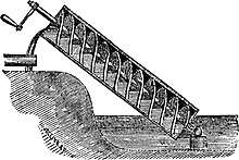
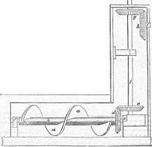
_21_335_1_Archimedische_Schraube_des_Dampfschiffes_Archimedes.PNG)
Apparently aware of the Royal Navy's view that screw propellers would prove unsuitable for seagoing service, Smith determined to prove this assumption wrong. In September 1837, he took his small vessel (now fitted with an iron propeller of a single turn) to sea, steaming from Blackwall, London to Hythe, Kent, with stops at Ramsgate, Dover and Folkestone. On the way back to London on the 25th, Smith's craft was observed making headway in stormy seas by officers of the Royal Navy. The Admiralty's interest in the technology was revived, and Smith was encouraged to build a full size ship to more conclusively demonstrate the technology's effectiveness.[23]
SS Archimedes was built in 1838 by Henry Wimshurst of London, as the world's first steamship[24] to be driven by a screw propeller.[25][26][27][28]
Archimedes had considerable influence on ship development, encouraging the adoption of screw propulsion by the Royal Navy, in addition to her influence on commercial vessels. Trials with Smith's Archimedes led to the famous tug-of-war competition in 1845 between the screw-driven HMS Rattler and the paddle steamer HMS Alecto; the former pulling the latter backward at 2.5 knots (4.6 km/h).
She also had a direct influence on the design of another innovative vessel, Isambard Kingdom Brunel's SS Great Britain in 1843, then the world's largest ship and the first screw-propelled steamship to cross the Atlantic Ocean in August 1845.
HMS Terror and HMS Erebus were both heavily modified to become the first Royal Navy ships to have steam-powered engines and screw propellers. Both participated in Franklin's lost expedition, last seen by Europeans in July 1845 near Baffin Bay.
Screw propeller design stabilized in the 1880s.
Shaftless propellers
Propellers without a central shaft consist of propeller blades attached to a ring which is part of a circle-shaped electric motor. This design is known as a Rim-driven thruster and has been used by some small, self-guided robotic ships. A boat with this type of propeller is known as an unscrewed surface vessel.
Aircraft propellers
The twisted aerofoil shape of modern aircraft propellers was pioneered by the Wright brothers. While some earlier engineers had attempted to model air propellers on marine propellers, the Wrights realized that a propeller is essentially the same as a wing, and were able to use data from their earlier wind tunnel experiments on wings. They also introduced a twist along the length of the blades. This was necessary to ensure the angle of attack of the blades was kept relatively constant along their length.[29] Their original propeller blades were only about 5% less efficient than the modern equivalent, some 100 years later.[30] The understanding of low speed propeller aerodynamics was fairly complete by the 1920s, but later requirements to handle more power in smaller diameter have made the problem more complex.
Alberto Santos Dumont, another early pioneer, applied the knowledge he gained from experiences with airships to make a propeller with a steel shaft and aluminium blades for his 14 bis biplane. Some of his designs used a bent aluminium sheet for blades, thus creating an airfoil shape. They were heavily undercambered, and this plus the absence of lengthwise twist made them less efficient than the Wright propellers. Even so, this was perhaps the first use of aluminium in the construction of an airscrew.
Propeller theory
History
In the second half of the nineteenth century, several theories were developed. The momentum theory or disk actuator theory – a theory describing a mathematical model of an ideal propeller – was developed by W.J.M. Rankine (1865), Alfred George Greenhill (1888) and R.E. Froude (1889). The propeller is modelled as an infinitely thin disc, inducing a constant velocity along the axis of rotation. This disc creates a flow around the propeller. Under certain mathematical premises of the fluid, there can be extracted a mathematical connection between power, radius of the propeller, torque and induced velocity. Friction is not included.
The blade element theory (BET) is a mathematical process originally designed by William Froude (1878), David W. Taylor (1893) and Stefan Drzewiecki to determine the behaviour of propellers. It involves breaking an airfoil down into several small parts then determining the forces on them. These forces are then converted into accelerations, which can be integrated into velocities and positions.
Theory of operation
 | |
|
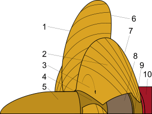
1) Trailing edge |
6) Leading edge |
A propeller is the most common propulsor on ships, imparting momentum to a fluid which causes a force to act on the ship. The ideal efficiency of any propulsor is that of an actuator disc in an ideal fluid. This is called the Froude efficiency and is a natural limit which cannot be exceeded by any device, no matter how good it is. Any propulsor which has virtually zero slip in the water, whether this is a very large propeller or a huge drag device, approaches 100% Froude efficiency. The essence of the actuator-disc theory is that if the slip is defined as the ratio of fluid velocity increase through the disc to vehicle velocity, the Froude efficiency is equal to 1/(slip + 1).[31] Thus a lightly loaded propeller with a large swept area can have a high Froude efficiency.
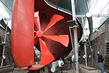
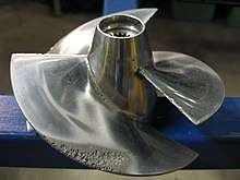
An actual propeller has blades made up of sections of helicoidal surfaces which can be thought to 'screw' through the fluid (hence the common reference to propellers as "screws"). Actually the blades are twisted airfoils or hydrofoils and each section contributes to the total thrust. Two to five blades are most common, although designs which are intended to operate at reduced noise will have more blades and one-bladed ones with a counterweight have also been used. Lightly loaded propellers for light aircraft and human-powered boats mostly have two blades, motor boats mostly have three blades. The blades are attached to a boss (hub), which should be as small as the needs of strength allow – with fixed-pitch propellers the blades and boss are usually a single casting.
An alternative design is the controllable-pitch propeller (CPP, or CRP for controllable-reversible pitch), where the blades are rotated normally to the drive shaft by additional machinery – usually hydraulics – at the hub and control linkages running down the shaft. This allows the drive machinery to operate at a constant speed while the propeller loading is changed to match operating conditions. It also eliminates the need for a reversing gear and allows for more rapid change to thrust, as the revolutions are constant. This type of propeller is most common on ships such as tugs where there can be enormous differences in propeller loading when towing compared to running free. The downsides of a CPP/CRP include: the large hub which decreases the torque required to cause cavitation, the mechanical complexity which limits transmission power and the extra blade shaping requirements forced upon the propeller designer.
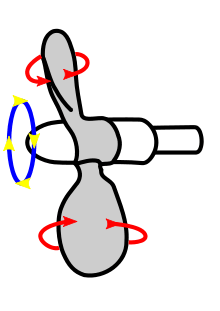
For smaller motors there are self-pitching propellers. The blades freely move through an entire circle on an axis at right angles to the shaft. This allows hydrodynamic and centrifugal forces to 'set' the angle the blades reach and so the pitch of the propeller.
A propeller that turns clockwise to produce forward thrust, when viewed from aft, is called right-handed. One that turns anticlockwise is said to be left-handed. Larger vessels often have twin screws to reduce heeling torque, counter-rotating propellers, the starboard screw is usually right-handed and the port left-handed, this is called outward turning. The opposite case is called inward turning. Another possibility is contra-rotating propellers, where two propellers rotate in opposing directions on a single shaft, or on separate shafts on nearly the same axis. Contra-rotating propellers offer increased efficiency by capturing the energy lost in the tangential velocities imparted to the fluid by the forward propeller (known as "propeller swirl"). The flow field behind the aft propeller of a contra-rotating set has very little "swirl", and this reduction in energy loss is seen as an increased efficiency of the aft propeller.
An azimuthing propeller is a propeller that turns around the vertical axis. The individual airfoil-shaped blades turn as the propeller moves so that they are always generating lift in the vessel's direction of movement. This type of propeller can reverse or change its direction of thrust very quickly.
Fixed-wing aircraft are also subject to the P-factor effect, in which a rotating propeller will yaw an aircraft slightly to one side because the relative wind it produces is asymmetrical. It is particularly noticeable when climbing, but is usually simple to compensate for with the aircraft's rudder. A more serious situation can exist if a multi-engine aircraft loses power to one of its engines, in particular the one which is positioned on the side that enhances the P-factor. This power plant is called the critical engine and its loss will require more control compensation by the pilot. Geometric pitch is the distance an element of an airplane propeller would advance in one revolution if it were moving along a helix having an angle equal to that between the chord of the element and a plane perpendicular to the propeller axis.
Marine propeller cavitation
Cavitation is the formation of vapor bubbles in water near a moving propeller blade in regions of low pressure due to Bernoulli's principle. It can occur if an attempt is made to transmit too much power through the screw, or if the propeller is operating at a very high speed. Cavitation can waste power, create vibration and wear, and cause damage to the propeller. It can occur in many ways on a propeller. The two most common types of propeller cavitation are suction side surface cavitation and tip vortex cavitation.
Suction side surface cavitation forms when the propeller is operating at high rotational speeds or under heavy load (high blade lift coefficient). The pressure on the upstream surface of the blade (the "suction side") can drop below the vapor pressure of the water, resulting in the formation of a vapor pocket. Under such conditions, the change in pressure between the downstream surface of the blade (the "pressure side") and the suction side is limited, and eventually reduced as the extent of cavitation is increased. When most of the blade surface is covered by cavitation, the pressure difference between the pressure side and suction side of the blade drops considerably, as does the thrust produced by the propeller. This condition is called "thrust breakdown". Operating the propeller under these conditions wastes energy, generates considerable noise, and as the vapor bubbles collapse it rapidly erodes the screw's surface due to localized shock waves against the blade surface.
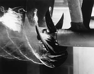
Tip vortex cavitation is caused by the extremely low pressures formed at the core of the tip vortex. The tip vortex is caused by fluid wrapping around the tip of the propeller; from the pressure side to the suction side. This video demonstrates tip vortex cavitation. Tip vortex cavitation typically occurs before suction side surface cavitation and is less damaging to the blade, since this type of cavitation doesn't collapse on the blade, but some distance downstream.
Cavitation can be used as an advantage in design of very high performance propellers, in the form of the supercavitating propeller. In this case, the blade section is designed such that the pressure side stays wetted while the suction side is completely covered by cavitation vapor. Because the suction side is covered with vapor instead of water it encounters very low viscous friction, making the supercavitating (SC) propeller comparably efficient at high speed. The shaping of SC blade sections however, make it inefficient at low speeds, when the suction side of the blade is wetted. (See also fluid dynamics).
A similar, but quite separate issue, is ventilation, which occurs when a propeller operating near the surface draws air into the blades, causing a similar loss of power and shaft vibration, but without the related potential blade surface damage caused by cavitation. Both effects can be mitigated by increasing the submerged depth of the propeller: cavitation is reduced because the hydrostatic pressure increases the margin to the vapor pressure, and ventilation because it is further from surface waves and other air pockets that might be drawn into the slipstream.
The blade profile of propellers designed to operate in a ventilated condition is often not of an aerofoil section and is a blunt ended taper instead. These are often known as "chopper" type propellers.
Forces acting on a foil
The force (F) experienced by a foil is determined by its area (A), fluid density (ρ), velocity (V) and the angle of the foil to the fluid flow, called angle of attack (), where:


The force has two parts – that normal to the direction of flow is lift (L) and that in the direction of flow is drag (D). Both can be expressed mathematically:
- and


where CL and CD are lift coefficient and drag coefficient respectively.
Each coefficient is a function of the angle of attack and Reynolds number. As the angle of attack increases lift rises rapidly from the no lift angle before slowing its increase and then decreasing, with a sharp drop as the stall angle is reached and flow is disrupted. Drag rises slowly at first and as the rate of increase in lift falls and the angle of attack increases drag increases more sharply.
For a given strength of circulation (), . The effect of the flow over and the circulation around the foil is to reduce the velocity over the face and increase it over the back of the blade. If the reduction in pressure is too much in relation to the ambient pressure of the fluid, cavitation occurs, bubbles form in the low pressure area and are moved towards the blade's trailing edge where they collapse as the pressure increases, this reduces propeller efficiency and increases noise. The forces generated by the bubble collapse can cause permanent damage to the surfaces of the blade.


Propeller thrust Equation
Single blade
Taking an arbitrary radial section of a blade at r, if revolutions are N then the rotational velocity is . If the blade was a complete screw it would advance through a solid at the rate of NP, where P is the pitch of the blade. In water the advance speed is rather lower, , the difference, or slip ratio, is:


where is the advance coefficient, and is the pitch ratio.


The forces of lift and drag on the blade, dA, where force normal to the surface is dL:

where:

These forces contribute to thrust, T, on the blade:

where:

As ,


From this total thrust can be obtained by integrating this expression along the blade. The transverse force is found in a similar manner:

Substituting for and multiplying by r, gives torque as:


which can be integrated as before.
The total thrust power of the propeller is proportional to and the shaft power to . So efficiency is . The blade efficiency is in the ratio between thrust and torque:


showing that the blade efficiency is determined by its momentum and its qualities in the form of angles and , where is the ratio of the drag and lift coefficients.


This analysis is simplified and ignores a number of significant factors including interference between the blades and the influence of tip vortices.
Thrust and torque
The thrust, T, and torque, Q, depend on the propeller's diameter, D, revolutions, N, and rate of advance, , together with the character of the fluid in which the propeller is operating and gravity. These factors create the following non-dimensional relationship:


where is a function of the advance coefficient, is a function of the Reynolds' number, and is a function of the Froude number. Both and are likely to be small in comparison to under normal operating conditions, so the expression can be reduced to:


For two identical propellers the expression for both will be the same. So with the propellers , and using the same subscripts to indicate each propeller:


For both Froude number and advance coefficient:

where is the ratio of the linear dimensions.

Thrust and velocity, at the same Froude number, give thrust power:

For torque:


Actual performance
When a propeller is added to a ship its performance is altered; there is the mechanical losses in the transmission of power; a general increase in total resistance; and the hull also impedes and renders non-uniform the flow through the propeller. The ratio between a propeller's efficiency attached to a ship () and in open water () is termed relative rotative efficiency.


The overall propulsive efficiency (an extension of effective power ()) is developed from the propulsive coefficient (), which is derived from the installed shaft power () modified by the effective power for the hull with appendages (), the propeller's thrust power (), and the relative rotative efficiency.


- / = hull efficiency =


- / = propeller efficiency =


- / = relative rotative efficiency =


- / = shaft transmission efficiency

Producing the following:

The terms contained within the brackets are commonly grouped as the quasi-propulsive coefficient (, ). The is produced from small-scale experiments and is modified with a load factor for full size ships.


Wake is the interaction between the ship and the water with its own velocity relative to the ship. The wake has three parts: the velocity of the water around the hull; the boundary layer between the water dragged by the hull and the surrounding flow; and the waves created by the movement of the ship. The first two parts will reduce the velocity of water into the propeller, the third will either increase or decrease the velocity depending on whether the waves create a crest or trough at the propeller.
Types of marine propellers
Controllable-pitch propeller
The controllable-pitch propeller has several advantages over the fixed-pitch variety. These include: the least drag depending on the speed used, the ability to move the sea vessel backwards, and the ability to use the "vane"-stance, which gives the least water resistance when not using the propeller (e.g. when the sails are used instead).
Skewback propeller
An advanced type of propeller used on German Type 212 submarines is called a skewback propeller. As in the scimitar blades used on some aircraft, the blade tips of a skewback propeller are swept back against the direction of rotation. In addition, the blades are tilted rearward along the longitudinal axis, giving the propeller an overall cup-shaped appearance. This design preserves thrust efficiency while reducing cavitation, and thus makes for a quiet, stealthy design.[32]
A small number of ships use propellers with winglets similar to those on some airplanes, reducing tip vortices and improving efficiency.[33][34][35][36][37]
Modular propeller
A modular propeller provides more control over the boat's performance. There is no need to change an entire prop, when there is an opportunity to only change the pitch or the damaged blades. Being able to adjust pitch will allow for boaters to have better performance while in different altitudes, water sports, and/or cruising.[38]
Voith Schneider propeller
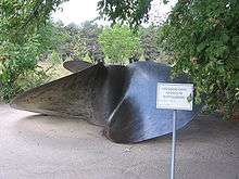
Voith Schneider propellers use four untwisted straight blades turning around a vertical axis instead of helical blades and can provide thrust in any direction at any time, at the cost of higher mechanical complexity.
Protection of small engines
For smaller engines, such as outboards, where the propeller is exposed to the risk of collision with heavy objects, the propeller often includes a device that is designed to fail when overloaded; the device or the whole propeller is sacrificed so that the more expensive transmission and engine are not damaged.
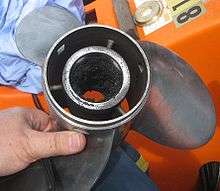
Typically in smaller (less than 10 hp or 7.5 kW) and older engines, a narrow shear pin through the drive shaft and propeller hub transmits the power of the engine at normal loads. The pin is designed to shear when the propeller is put under a load that could damage the engine. After the pin is sheared the engine is unable to provide propulsive power to the boat until a new shear pin is fitted.[39]
In larger and more modern engines, a rubber bushing transmits the torque of the drive shaft to the propeller's hub. Under a damaging load the friction of the bushing in the hub is overcome and the rotating propeller slips on the shaft, preventing overloading of the engine's components.[40] After such an event the rubber bushing may be damaged. If so, it may continue to transmit reduced power at low revolutions, but may provide no power, due to reduced friction, at high revolutions. Also, the rubber bushing may perish over time leading to its failure under loads below its designed failure load.
Whether a rubber bushing can be replaced or repaired depends upon the propeller; some cannot. Some can, but need special equipment to insert the oversized bushing for an interference fit. Others can be replaced easily. The "special equipment" usually consists of a funnel, a press and rubber lubricant (soap). If one does not have access to a lathe, an improvised funnel can be made from steel tube and car body filler; as the filler is only subject to compressive forces it is able to do a good job. Often, the bushing can be drawn into place with nothing more complex than a couple of nuts, washers and a threaded rod. A more serious problem with this type of propeller is a "frozen-on" spline bushing, which makes propeller removal impossible. In such cases the propeller must be heated in order to deliberately destroy the rubber insert. Once the propeller is removed, the splined tube can be cut away with a grinder and a new spline bushing is then required. To prevent a recurrence of the problem, the splines can be coated with anti-seize anti-corrosion compound.
In some modern propellers, a hard polymer insert called a drive sleeve replaces the rubber bushing. The splined or other non-circular cross section of the sleeve inserted between the shaft and propeller hub transmits the engine torque to the propeller, rather than friction. The polymer is weaker than the components of the propeller and engine so it fails before they do when the propeller is overloaded.[41] This fails completely under excessive load, but can easily be replaced.
Propeller variations
Cleaver
A cleaver is a type of propeller design especially used for boat racing. Its leading edge is formed round, while the trailing edge is cut straight. It provides little bow lift, so that it can be used on boats that do not need much bow lift, for instance hydroplanes, that naturally have enough hydrodynamic bow lift. To compensate for the lack of bow lift, a hydrofoil may be installed on the lower unit. Hydrofoils reduce bow lift and help to get a boat out of the hole and onto plane.
See also
- Screw-propelled vehicle – Vehicle propelled by load-bearing rotating helical flanges
Propeller characteristics
- Advance ratio – Ratio of freestream speed to tip speed
- Axial fan design
Propeller phenomena
- Propeller walk – Tendency of a propeller to yaw a vessel during acceleration
- Cavitation – Formation of vapour-filled low-pressure voids in a liquid
Other
- Adjustable pitch propeller
- Azimuth thruster – Steerable propulsion pod under a watercraft
- Azipod – Electric drive azimuth thruster
- Bow/stern thruster – Transverse or steerable propulsion device in a watercraft
- Controllable pitch propeller
- Ducted propeller – Marine propeller with a non-rotating nozzle
- Pump-jet – Marine propulsion system
- Folding propeller – Propeller with blades that fold open when rotating
- Helix – Type of smooth space curve
- Impeller – Rotor used to increase (or decrease in case of turbines) the pressure and flow of a fluid or gas
- Kitchen rudder – Type of directional propulsion system for vessels
- Modular propeller
- Paddle steamer – Steam powered vessel propelled by paddle wheels
- Pleuger rudder – A thruster assisted ship's rudder
- Propulsor – A machinical device to propel a vessel
- Supercavitating propeller – Marine propeller designed to operate with a full cavitation bubble
- Variable-pitch propeller – Propeller with blades that can be rotated to control their pitch while in use
- Voith-Schneider propeller – Perpendicular axis marine propulsion system
- Wake-equalising duct – Ship hull appendage to modify propeller inflow
Materials and manufacture
- Balancing machine
- Composite materials
Notes
- "Propeller". Encyclopedia Britannica. Retrieved 2019-12-04.
- "NASA website article - Propeller Propulsion". May 5, 2015.
- Carlton, John, Marine Propellers and Propulsion Butterworth-Heinemann, 2012, p. 363
- Carlton, p. 1
- Bourne, John (April 10, 1855). "A Treatise on the Screw Propeller: With Various Suggestions of Improvement". Longman, Brown, Green, and Longmans – via Google Books.
- "Patents for Inventions: Abridgments of Specifications : Class ..." Patent Office. April 10, 1857 – via Google Books.
- Murihead, James Patrick, The Life of James Watt, with Selections from His Correspondence ... With Portraits and Woodcuts, London: John Murray, 1858, p. 208
- Stein, Stephen K. The Sea in World History: Exploration, Travel, and Trade [2 volumes], Editor Stephen K. Stein, ABC-CLIO, 2017, Volume 1, p. 600
- Manstan, Roy R.; Frese, Frederic J., Turtle: David Bushnell's Revolutionary Vessel, Yardley, Pa: Westholme Publishing. ISBN 978-1-59416-105-6. OCLC 369779489, 2010, pp. xiii, 52, 53
- Tucker, Spencer, Almanac of American Military History, ABC-CLIO, 2013, Volume 1, p. 305
- Mansten pp. xiii, xiv
- Nicholson, William, A Journal of Natural Philosophy, Chemistry and the Arts, Volume 4, G. G. and J. Robinson, 1801, p. 221
- Manstan, p.150
- Carlton, pp. 1–2
- Carlton, p.2
- Paul Augustin Normand, La Genèse de l'Hélice Propulsive (The Genesis of the Screw Propulsor). Paris: Académie de Marine, 1962, pp. 31–50.
- Mario Theriault, Great Maritime Inventions Goose Lane Publishing (2001) pp. 58–59
- ""Patch's Propeller", Scientific America, Vol. 4, No. 5 (October 10, 1848) p. 33, featured in The Archimedes Screw website retrieved 31 January 2010". Archived from the original on July 8, 2011.
- Smith, Edgar C. (1905). A Short history of Naval and Marine Engineering. University Press, Cambridge. pp. 66–67.
- Bourne, p. 84.
- In the case of Francis B. Ogden, Symonds was correct. Ericsson had made the mistake of placing the rudder forward of the propellers, which made the rudder ineffective. Symonds believed that Ericsson tried to disguise the problem by towing a barge during the test.
- Bourne, pp. 87–89.
- Bourne, p. 85.
- The emphasis here is on ship. There were a number of successful propeller-driven vessels prior to Archimedes, including Smith's own Francis Smith and Ericsson's Francis B. Ogden and Robert F. Stockton. However, these vessels were boats – designed for service on inland waterways – as opposed to ships, built for seagoing service.
- "The type of screw propeller that now propels the vast majority of boats and ships was patented in 1836, first by the British engineer Francis Pettit Smith, then by the Swedish engineer John Ericsson. Smith used the design in the first successful screw-driven steamship, Archimedes, which was launched in 1839.". Marshall Cavendish, p. 1335.
- "The propeller was invented in 1836 by Francis Pettit Smith in Britain and John Ericsson in the United States. It first powered a seagoing ship, appropriately called Archimedes, in 1839." Macauley and Ardley, p. 378.
- "In 1839, the Messrs. Rennie constructed the engines, machinery and propeller, for the celebrated Archimedes, from which may be said to date the introduction of the screw system of propulsion ...". Mechanics Magazine, p. 220.
- "It was not until 1839 that the principle of propelling steamships by a screw blade was fairly brought before the world, and for this we are indebted, as almost every adult will remember, to Mr. F. P. Smith of London. He was the man who first made the screw propeller practically useful. Aided by spirited capitalists, he built a large steamer named the "Archimedes", and the results obtained from her at once arrested public attention.". MacFarlane, p. 109.
- Pilot's Handbook of Aeronautical Knowledge. Oklahoma City: U.S. Federal Aviation Administration. 2008. pp. 2–7. FAA-8083-25A.
- Ash, Robert L., Colin P. Britcher and Kenneth W. Hyde. "Wrights: How two brothers from Dayton added a new twist to airplane propulsion." Mechanical Engineering: 100 years of Flight, 3 July 2007.
- Schmidt, Theo. "Propeller simulation with PropSim" (PDF). Human Power Number 48.
- "SILENT propellers". www.francehelices.fr. JMCWebCreation and Co. 2009. Archived from the original on September 26, 2007. Retrieved July 21, 2017.
- Godske, Bjørn. "Energy saving propeller" (in Danish) Ingeniøren, 23 April 2012. Accessed: 15 March 2014. English translation
- Godske, Bjørn. "Kappel-propellers pave the way for success at MAN" (in Danish) Ingeniøren, 15 March 2014. Accessed: 15 March 2014. English translation
- "Kappel agreement secures access to major market" 30 August 2013.
- "KAPRICCIO Project Archived 2014-03-15 at the Wayback Machine" European Union. Accessed: 15 March 2014.
- "Industry Pays Tribute to Innovation Awards Winners" Marine link, 3 October 2002. Accessed: 15 March 2014. Quote: "Winner: the energy-saving Kappel propeller concept from the European Commission-funded Kapriccio propulsion research project. Blades curved towards the tips on the suction side reduce energy losses, fuel consumption, noise and vibration"
- Smrcka, Karel (March 18, 2005). "A new start for marine propellers". Engineering News. Retrieved July 21, 2017.
- Getchell, David (1994), The Outboard Boater's Handbook, ISBN 9780070230538
- Ministry Of Defence (Navy), Great Britain (1995), Admiralty Manual of Seamanship, ISBN 9780117726963
- US, "Torsionally twisting propeller drive sleeve and adapter", published March 8, 1994, issued January 16, 1996
External links
| Wikimedia Commons has media related to Propellers. |
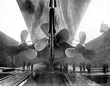
- Titanic's Propellers
- Theory calculation propellers and wings: detailed article with blade element theory software application
- "What You Should Know About Propellers For Our Fighting Planes", November 1943, Popular Science extremely detailed article with numerous drawings and cutaway illustrations
- Archimedes Screw History: The story of marine propulsion
- propellers history: The story of propellers
- Propulsors and gears: Wartsila Marine Propellers