Node (circuits)
In electrical engineering, a node is any point on a circuit where the terminals of two or more circuit elements meet. In circuit diagrams, connections are ideal wires with zero resistance, so a node may consist of the entire section of wire between elements, not just a single point.[1]
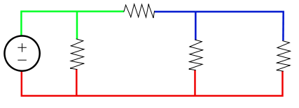
Each color in the circuit represents one node.
According to Ohm's law, V = IR, the voltage across any two points of a node with negligible resistance is

showing that the voltage at every point of a node is the same. However, there are some notable exceptions where the voltage difference is large enough to become significant:
- High-precision resistance measurements using a Kelvin connection
- The difference in voltage between ground and neutral, between the neutral wire and the ground in domestic AC power plugs and sockets, can be fatal. A properly installed electrical system connects them together at only one location, leading many people to the fatally incorrect conclusion that they are at "the same" voltage, or that the safety ground is "redundant and unnecessary"
- The Seebeck effect and the Peltier effect
- Joints involving aluminium wire
Dots used to mark nodes on a circuit diagram are sometimes referred to as meatballs.[2]
References
- Smith, Ralph J. (1966), Circuits, Devices and Systems, Chapter 2, John Wiley & Sons, Library of Congress Catalog Card No.: 66-17612
- Mansfield, Michael; O'Sullivan, Colm (2010), Understanding Physics (2nd edition), Chapter 14, page 359, John Wiley & Sons
This article is issued from Wikipedia. The text is licensed under Creative Commons - Attribution - Sharealike. Additional terms may apply for the media files.