N-localizer
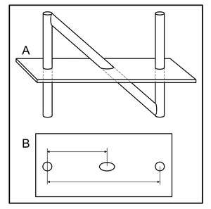
The N-localizer[3] or N-bar is a device that enables guidance of stereotactic surgery or radiosurgery using tomographic images that are obtained via computed tomography (CT),[4] magnetic resonance imaging (MRI),[5] or positron emission tomography (PET).[6] The N-localizer comprises a diagonal rod that spans two vertical rods to form an N-shape (Figure 1) that permits calculation of the point where a tomographic image plane intersects the diagonal rod. Attaching three N-localizers to a stereotactic instrument allows calculation of three points where a tomographic image plane intersects three diagonal rods (Figure 2). These points determine the spatial orientation of the tomographic image plane relative to the stereotactic instrument.[7]
| N-localizer | |
|---|---|
 Three N-localizers attached to a stereotactic instrument.[1] | |
| Specialty | neurosurgery, radiation oncology |
| Intervention | stereotactic surgery, radiosurgery |
| Inventor(s) | Russell A. Brown[2] |
An alternative to the N-localizer is the Sturm-Pastyr localizer that comprises three rods wherein two diagonal rods form a V-shape and a vertical rod is positioned midway between the two diagonal rods.[8] Compared to the N-localizer, the Sturm-Pastyr localizer requires more elaborate calculations to determine the spatial orientation of the tomographic image plane;[9] and in contrast to the N-localizer, calculations for the Sturm-Pastyr localizer require accurate specification of the pixel size in the tomographic image.[10]
Figures

References
- Arle, J (2009). "Development of a Classic: The Todd-Wells Apparatus, the BRW, and the CRW Stereotactic Frames". In Lozano, AM; Gildenberg, PL; Tasker, RR (eds.). Textbook of Stereotactic and Functional Neurosurgery. Berlin: Springer-Verlag. pp. 456–460. doi:10.1007/978-3-540-69960-6. ISBN 978-3-540-69959-0.
- "System Using Computed Tomography as for Selective Body Treatment". U.S. Patent 4608977. 1986.
- Galloway, RL Jr. (2015). "Introduction and Historical Perspectives on Image-Guided Surgery". In Golby, AJ (ed.). Image-Guided Neurosurgery. Amsterdam: Elsevier. pp. 2–4. doi:10.1016/B978-0-12-800870-6.00001-7. ISBN 978-0-12-800870-6.
- Thomas DG, Anderson RE, du Boulay GH (1984). "CT-guided stereotactic neurosurgery: experience in 24 cases with a new stereotactic system". Journal of Neurology, Neurosurgery & Psychiatry. 47 (1): 9–16. doi:10.1136/jnnp.47.1.9. PMC 1027634. PMID 6363629.
- Heilbrun MP, Sunderland PM, McDonald PR, Wells TH Jr, Cosman E, Ganz E (1987). "Brown-Roberts-Wells stereotactic frame modifications to accomplish magnetic resonance imaging guidance in three planes". Applied Neurophysiology. 50 (1–6): 143–152. doi:10.1159/000100700. PMID 3329837.
- Maciunas RJ, Kessler RM, Maurer C, Mandava V, Watt G, Smith G (1992). "Positron emission tomography imaging-directed stereotactic neurosurgery". Stereotactic and Functional Neurosurgery. 58 (1–4): 134–140. doi:10.1159/000098986. PMID 1439330.
- Gildenberg, PL; Krauss, JK (2009). "History of Stereotactic Surgery". In Lozano, AM; Gildenberg, PL; Tasker, RR (eds.). Textbook of Stereotactic and Functional Neurosurgery. Berlin: Springer-Verlag. p. 23. doi:10.1007/978-3-540-69960-6. ISBN 978-3-540-69959-0.
- Sturm V, Pastyr O, Schlegel W, Scharfenberg H, Zabel HJ, Netzeband G, Schabbert S, Berberich W (1983). "Stereotactic computer tomography with a modified Riechert-Mundinger device as the basis for integrated stereotactic neuroradiological investigations". Acta Neurochirurgica. 68 (1–2): 11–17. doi:10.1007/BF01406197. PMID 6344559.
- Dai J, Zhu Y, Qu H, Hu Y (2001). "An algorithm for stereotactic localization by computed tomography or magnetic resonance imaging". Physics in Medicine and Biology. 46 (1): N1–N7. doi:10.1088/0031-9155/46/1/401. PMID 11197682.
- Weaver K, Smith V, Lewis JD, Lulu B, Barnett CM, Leibel SA, Gutin P, Larson D, Phillips T (1990). "A CT-based computerized treatment planning system for I-125 stereotactic brain implants". International Journal of Radiation Oncology, Biology, Physics. 18 (2): 445–454. doi:10.1016/0360-3016(90)90114-Y. PMID 2406230.
Further reading
- Tse, VCK; Kalani, MYS; Adler, JR (2015). "Techniques of Stereotactic Localization". In Chin, LS; Regine, WF (eds.). Principles and Practice of Stereotactic Radiosurgery. New York: Springer. pp. 25–32. doi:10.1007/978-1-4614-8363-2. ISBN 978-1-4614-8362-5.
- Saleh, H; Kassas, B (2014). "Developing Stereotactic Frames for Cranial Treatment". In Benedict, SH; Schlesinger, DJ; Goetsche, SJ; Kavanagh, BD (eds.). Stereotactic Radiosurgery and Stereotactic Body Radiation Therapy. Boca Raton: CRC Press. pp. 156–159. doi:10.1201/b16776. ISBN 978-1-4398-4198-3.