Mechanism (engineering)
In engineering, a mechanism is a device that transforms input forces and movement into a desired set of output forces and movement. Mechanisms generally consist of moving components that can include:
- Gears and gear trains
- Belt and chain drives
- Cam and followers
- Linkage
- Friction devices, such as brakes and clutches
- Structural components such as a frame, fasteners, bearings, springs, lubricants
- Various machine elements, such as splines, pins, and keys.
The German scientist Reuleaux provides the definition "a machine is a combination of resistant bodies so arranged that by their means the mechanical forces of nature can be compelled to do work accompanied by certain determinate motion." In this context, his use of machine is generally interpreted to mean mechanism.
The combination of force and movement defines power, and a mechanism manages power to achieve a desired set of forces and movement.
A mechanism is usually a piece of a larger process or mechanical system. Sometimes an entire machine may be referred to as a mechanism. Examples are the steering mechanism in a car, or the winding mechanism of a wristwatch. Multiple mechanisms are machines.
Kinematic Pairs
From the time of Archimedes through the Renaissance, mechanisms were viewed as constructed from simple machines, such as the lever, pulley, screw, wheel and axle, wedge, and inclined plane. Reuleaux focused on bodies, called links, and the connections between these bodies called kinematic pairs, or joints.
To use geometry to study the movement of a mechanism, its links are modeled as rigid bodies. This means that distances between points in a link are assumed to not change as the mechanism moves that is, the link does not flex. Thus, the relative movement between points in two connected links is considered to result from the kinematic pair that joins them.
Kinematic pairs, or joints, are considered to provide ideal constraints between two links, such as the constraint of a single point for pure rotation, or the constraint of a line for pure sliding, as well as pure rolling without slipping and point contact with slipping. A mechanism is modeled as an assembly of rigid links and kinematic pairs.

Links and joints
Reuleaux called the ideal connections between links kinematic pairs. He distinguished between higher pairs with line contact between the two links and lower pairs with area contact between the links. J. Phillips shows that there are many ways to construct pairs that do not fit this simple model.
Lower pair: A lower pair is an ideal joint that has surface contact between the pair of elements, as in the following cases:
- A revolute pair, or hinged joint, requires a line in the moving body to remain co-linear with a line in the fixed body, and a plane perpendicular to this line in the moving body must maintain contact with a similar perpendicular plane in the fixed body. This imposes five constraints on the relative movement of the links, which therefore has one degree of freedom.
- A prismatic joint, or slider, requires that a line in the moving body remain co-linear with a line in the fixed body, and a plane parallel to this line in the moving body must maintain contact with a similar parallel plane in the fixed body. This imposes five constraints on the relative movement of the links, which therefore has one degree of freedom.
- A cylindrical joint requires that a line in the moving body remain co-linear with a line in the fixed body. It combines a revolute joint and a sliding joint. This joint has two degrees of freedom.
- A spherical joint, or ball joint, requires that a point in the moving body maintain contact with a point in the fixed body. This joint has three degrees of freedom.
- A planar joint requires that a plane in the moving body maintain contact with a plane in fixed body. This joint has three degrees of freedom.
- A screw joint, or helical joint, has only one degree of freedom because the sliding and rotational motions are related by the helix angle of the thread.
Higher pairs: Generally, a higher pair is a constraint that requires a line or point contact between the elemental surfaces. For example, the contact between a cam and its follower is a higher pair called a cam joint. Similarly, the contact between the involute curves that form the meshing teeth of two gears are cam joints.

Kinematic diagram
A kinematic diagram reduces the machine components to a skeleton diagram that emphasizes the joints and reduces the links to simple geometric elements. This diagram can also be formulated as a graph by representing the links of the mechanism as vertices and the joints as edges of the graph. This version of the kinematic diagram has proven effective in enumerating kinematic structures in the process of machine design.[1]
An important consideration in this design process is the degree of freedom of the system of links and joints, which is determined using the Chebychev–Grübler–Kutzbach criterion.

Planar mechanisms
While all mechanisms in a mechanical system are three-dimensional, they can be analyzed using plane geometry, if the movement of the individual components are constrained so all point trajectories are parallel or in a series connection to a plane. In this case the system is called a planar mechanism. The kinematic analysis of planar mechanisms uses the subset of Special Euclidean group SE, consisting of planar rotations and translations, denote SE.
The group SE is three-dimensional, which means that every position of a body in the plane is defined by three parameters. The parameters are often the x and y coordinates of the origin of a coordinate frame in M measured from the origin of a coordinate frame in F, and the angle measured from the x-axis in F to the x-axis in M. This is often described saying a body in the plane has three degrees-of-freedom.
The pure rotation of a hinge and the linear translation of a slider can be identified with subgroups of SE , and define the two joints one degree-of-freedom joints of planar mechanisms. The cam joint formed by two surfaces in sliding and rotating contact is a two degree-of-freedom joint.
See Theo Jansen's Strandbeest walking machine with legs constructed from planar eight-bar linkages
Spherical mechanisms
It is possible to construct a mechanism such that the point trajectories in all components lie in concentric spherical shells around a fixed point. An example is the gimbaled gyroscope. These devices are called spherical mechanisms.[2] Spherical mechanisms are constructed by connecting links with hinged joints such that the axes of each hinge passes through the same point. This point becomes center of the concentric spherical shells. The movement of these mechanisms is characterized by the group SO(3) of rotations in three-dimensional space. Other examples of spherical mechanisms are the automotive differential and the robotic wrist.
Select this link for an animation of a Spherical deployable mechanism.
The rotation group SO(3) is three-dimensional. An example of the three parameters that specify a spatial rotation are the roll, pitch and yaw angles used to define the orientation of an aircraft.
Spatial mechanisms

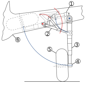
A mechanism in which a body moves through a general spatial movement is called a spatial mechanism. An example is the RSSR linkage, which can be viewed as a four-bar linkage in which the hinged joints of the coupler link are replaced by rod ends, also called spherical joints or ball joints. The rod ends let the input and output cranks of the RSSR linkage be misaligned to the point that they lie in different planes, which causes the coupler link to move in a general spatial movement. Robot arms, Stewart platforms, and humanoid robotic systems are also examples of spatial mechanisms.
Bennett's linkage is an example of a spatial overconstrained mechanism, which is constructed from four hinged joints.
The group SE(3) is six-dimensional, which means the position of a body in space is defined by six parameters. Three of the parameters define the origin of the moving reference frame relative to the fixed frame. Three other parameters define the orientation of the moving frame relative to the fixed frame.
Linkages

A linkage is a collection of links connected by joints. Generally, the links are the structural elements and the joints allow movement. Perhaps the single most useful example is the planar four-bar linkage. However, there are many more special linkages:
- Watt's linkage is a four-bar linkage that generates an approximate straight line. It was critical to the operation of his design for the steam engine. This linkage also appears in vehicle suspensions to prevent side-to-side movement of the body relative to the wheels. Also see the article Parallel motion.
- The success of Watt's linkage lead to the design of similar approximate straight-line linkages, such as Hoeken's linkage and Chebyshev's linkage.
- The Peaucellier linkage generates a true straight-line output from a rotary input.
- The Sarrus linkage is a spatial linkage that generates straight-line movement from a rotary input.
- The Klann linkage and the Jansen linkage are recent inventions that provide interesting walking movements. They are respectively a six-bar and an eight-bar linkage.
Compliant mechanisms
A compliant mechanism is a series of rigid bodies connected by compliant elements. These mechanisms have many advantages, including reduced part-count, reduced "slop" between joints (no parasitic motion because of gaps between parts), energy storage, low maintenance (they don't require lubrication and there is low mechanical wear), and ease of manufacture [3].
Flexure bearings (also known as flexure joints) are a subset of compliant mechanisms that produce a geometrically well-defined motion (rotation) on application of a force.
Cam and follower mechanisms
A cam and follower is formed by the direct contact of two specially shaped links. The driving link is called the cam (also see cam shaft) and the link that is driven through the direct contact of their surfaces is called the follower. The shape of the contacting surfaces of the cam and follower determines the movement of the mechanism. In general a cam follower mechanism's energy is transferred from cam to follower. The cam shaft is rotated and, according to the cam profile, the follower moves up and down. Now slightly different types of eccentric cam followers are also available in which energy is transferred from the follower to the cam. The main benefit of this type of cam follower mechanism is that the follower moves a little bit and helps to rotate the cam 6 times more circumference length with 70% force.
Gears and gear trains
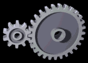
The transmission of rotation between contacting toothed wheels can be traced back to the Antikythera mechanism of Greece and the south-pointing chariot of China. Illustrations by the renaissance scientist Georgius Agricola show gear trains with cylindrical teeth. The implementation of the involute tooth yielded a standard gear design that provides a constant speed ratio. Some important features of gears and gear trains are:
- The ratio of the pitch circles of mating gears defines the speed ratio and the mechanical advantage of the gear set.
- A planetary gear train provides high gear reduction in a compact package.
- It is possible to design gear teeth for gears that are non-circular, yet still transmit torque smoothly.
- The speed ratios of chain and belt drives are computed in the same way as gear ratios. (See bicycle gearing.)
Mechanism synthesis
The design of mechanisms to achieve a particular movement and force transmission is known as the kinematic synthesis of mechanisms.[4] This is a set of geometric techniques that yield the dimensions of linkages, cam and follower mechanisms, and gears and gear trains to perform a required mechanical movement and power transmission.[5]
See also
- Gear train
- Linkage (mechanical)
- Machine (mechanical)
- Mechanical system
- Mechanical watch
- Outline of machines
- Virtual work
- Hoberman mechanism
References
- Lung-Wen Tsai, 2001, Mechanism design: enumeration of kinematic structures according to function, CRC Press
- J. M. McCarthy and G. S. Soh, Geometric Design of Linkages, 2nd Edition, Springer 2010
- "Compliant Mechanisms | About Compliant Mechanisms". compliantmechanisms. Retrieved 2019-02-08.
- Hartenberg, R.S. and J. Denavit (1964) Kinematic synthesis of linkages, New York: McGraw-Hill — Online link from Cornell University.
- J. J. Uicker, G. R. Pennock, and J. E. Shigley, Theory of Machines and Mechanisms, Fifth Ed., Oxford University Press, 2016.
External links
| Wikimedia Commons has media related to Mechanisms (engineering). |
- Balanced hinge-lever mechanism
- 507 Mechanical Movements a 1908 publication by Henry T. Brown
- Machines and Mechanisms Wiki
- Kinematic Models for Design Digital Library (KMODDL) collections of movies and photos of hundreds of mechanism models.
- A six-bar straight-line linkage in the collection of Reuleaux models at Cornell University
- Animations of a variety of mechanisms.
- Example of a six-bar function generator that computes the angle for a given range.
- A variety of linkage animations.
- A variety of six-bar linkage designs.