Jones calculus
In optics, polarized light can be described using the Jones calculus, discovered by R. C. Jones in 1941. Polarized light is represented by a Jones vector, and linear optical elements are represented by Jones matrices. When light crosses an optical element the resulting polarization of the emerging light is found by taking the product of the Jones matrix of the optical element and the Jones vector of the incident light. Note that Jones calculus is only applicable to light that is already fully polarized. Light which is randomly polarized, partially polarized, or incoherent must be treated using Mueller calculus.
The Jones vector
The Jones vector describes the polarization of light in free space or another homogeneous isotropic non-attenuating medium, where the light can be properly described as transverse waves. Suppose that a monochromatic plane wave of light is travelling in the positive z-direction, with angular frequency ω and wavevector k = (0,0,k), where the wavenumber k = ω/c. Then the electric and magnetic fields E and H are orthogonal to k at each point; they both lie in the plane "transverse" to the direction of motion. Furthermore, H is determined from E by 90-degree rotation and a fixed multiplier depending on the wave impedance of the medium. So the polarization of the light can be determined by studying E. The complex amplitude of E is written

Note that the physical E field is the real part of this vector; the complex multiplier serves up the phase information. Here is the imaginary unit with .


The Jones vector is then

Thus, the Jones vector represents the amplitude and phase of the electric field in the x and y directions.
The sum of the squares of the absolute values of the two components of Jones vectors is proportional to the intensity of light. It is common to normalize it to 1 at the starting point of calculation for simplification. It is also common to constrain the first component of the Jones vectors to be a real number. This discards the overall phase information that would be needed for calculation of interference with other beams.
Note that all Jones vectors and matrices in this article employ the convention that the phase of the light wave is given by , a convention used by Hecht. Under this convention, increase in (or ) indicates retardation (delay) in phase, while decrease indicates advance in phase. For example, a Jones vectors component of () indicates retardation by (or 90 degree) compared to 1 (). Circular polarisation described under Jones' convention is called : "From the point of view of the receiver". Collett uses the opposite definition for the phase (). Circular polarisation described under Collett's convention is called : "From the point of view of the source". The reader should be wary of the choice of convention when consulting references on the Jones calculus.


The following table gives the 6 common examples of normalized Jones vectors.
| Polarization | Jones vector | Typical ket notation |
|---|---|---|
| Linear polarized in the x direction Typically called "horizontal" | ||
| Linear polarized in the y direction Typically called "vertical" | ||
| Linear polarized at 45° from the x axis Typically called "diagonal" L+45 | ||
| Linear polarized at −45° from the x axis Typically called "anti-diagonal" L−45 | ||
| Right-hand circular polarized Typically called "RCP" or "RHCP" | ||
| Left-hand circular polarized Typically called "LCP" or "LHCP" |


A general vector that points to any place on the surface is written as a ket . When employing the Poincaré sphere (also known as the Bloch sphere), the basis kets ( and ) must be assigned to opposing (antipodal) pairs of the kets listed above. For example, one might assign = and = . These assignments are arbitrary. Opposing pairs are


- and
- and
- and


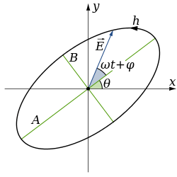
The polarization of any point not equal to or and not on the circle that passes through is known as elliptical polarization.

Jones matrices
The Jones matrices are operators that act on the Jones vectors defined above. These matrices are implemented by various optical elements such as lenses, beam splitters, mirrors, etc. Each matrix represents projection onto a one-dimensional complex subspace of the Jones vectors. The following table gives examples of Jones matrices for polarizers:
| Optical element | Jones matrix |
| Linear polarizer with axis of transmission horizontal[1] |
|
| Linear polarizer with axis of transmission vertical[1] |
|
| Linear polarizer with axis of transmission at ±45° with the horizontal[1] |
|
| Linear polarizer with axis of transmission angle from the horizontal[1] |
|
| Right circular polarizer[1] |
|
| Left circular polarizer[1] |
|


Phase retarders
Phase retarders introduce a phase shift between the vertical and horizontal component of the field and thus change the polarization of the beam. Phase retarders are usually made out of birefringent uniaxial crystals such as calcite, MgF2 or quartz. Uniaxial crystals have one crystal axis that is different from the other two crystal axes (i.e., ni ≠ nj = nk). This unique axis is called the extraordinary axis and is also referred to as the optic axis. An optic axis can be the fast or the slow axis for the crystal depending on the crystal at hand. Light travels with a higher phase velocity along an axis that has the smallest refractive index and this axis is called the fast axis. Similarly, an axis which has the largest refractive index is called a slow axis since the phase velocity of light is the lowest along this axis. "Negative" uniaxial crystals (e.g., calcite CaCO3, sapphire Al2O3) have ne < no so for these crystals, the extraordinary axis (optic axis) is the fast axis, whereas for "positive" uniaxial crystals (e.g., quartz SiO2, magnesium fluoride MgF2, rutile TiO2), ne > n o and thus the extraordinary axis (optic axis) is the slow axis.
Any phase retarder with fast axis equal to the x- or y-axis has zero off-diagonal terms and thus can be conveniently expressed as

where and are the phase offsets of the electric fields in and directions respectively. In the phase convention , define the relative phase between the two waves as . Then a positive (i.e. > ) means that doesn't attain the same value as until a later time, i.e. leads . Similarly, if , then leads .


For example, if the fast axis of a quarter wave plate is horizontal, then the phase velocity along the horizontal direction is ahead of the vertical direction i.e., leads . Thus, which for a quarter wave plate yields .


In the opposite convention , define the relative phase as . Then means that doesn't attain the same value as until a later time, i.e. leads .


| Phase retarders | Corresponding Jones matrix |
|---|---|
| Quarter-wave plate with fast axis vertical[2][note 1] | |
| Quarter-wave plate with fast axis horizontal[2] | |
| Quarter-wave plate with fast axis at angle w.r.t the horizontal axis | |
| Half-wave plate with fast axis at angle w.r.t the horizontal axis[3] | |
| Arbitrary birefringent material (as phase retarder)[4] |


The special expressions for the phase retarders can be obtained by taking suitable parameter values in the general expression for a birefringent material. In the general expression:
- The relative phase retardation induced between the fast axis and the slow axis is given by
- is the orientation of the fast axis with respect to the x-axis.
- is the circularity.


Note that for linear retarders, = 0 and for circular retarders, = ± /2, = /4. In general for elliptical retarders, takes on values between - /2 and /2.

Axially rotated elements
Assume an optical element has its optic axis perpendicular to the surface vector for the plane of incidence and is rotated about this surface vector by angle θ/2 (i.e., the principal plane, through which the optic axis passes, makes angle θ/2 with respect to the plane of polarization of the electric field of the incident TE wave). Recall that a half-wave plate rotates polarization as twice the angle between incident polarization and optic axis (principal plane). Therefore, the Jones matrix for the rotated polarization state, M(θ), is
- where


This agrees with the expression for a half-wave plate in the table above. These rotations are identical to beam unitary splitter transformation in optical physics given by

where the primed and unprimed coefficients represent beams incident from opposite sides of the beam splitter. The reflected and transmitted components acquire a phase θr and θt, respectively. The requirements for a valid representation of the element are [5]

and

- Both of these representations are unitary matrices fitting these requirements; and as such, are both valid.
Arbitrarily rotated elements
This would involve a three-dimensional rotation matrix. See Russell A. Chipman[6] and Garam Yun for work done on this.[7][8][9]
Polarization axis from Jones vector
The angle of polarization ellipse of the Jones vector can be calculated as below,


where is the angle of either a major or a minor axis and is a reflection matrix.

Notes


References
- Fowles, G. (1989). Introduction to Modern Optics (2nd ed.). Dover. p. 35.
- Eugene Hecht (2001). Optics (4th ed.). p. 378. ISBN 978-0805385663.
- Gerald, A.; Burch, J.M. (1975). Introduction to Matrix Methods in Optics (1st ed.). John Wiley & Sons. p. 212. ISBN 978-0471296850.
- Jose Jorge Gill and Eusebio Bernabeu (1987) "Obtainment of the polarizing and retardation parameters of a non-depolarizing optical system from the polar decomposition of its Mueller matrix", Optik, 76: 67-71
- Am. J. Phys. 57 (1), 66 (1989).
- Russell A. Chipman (1995) "Mechanics of polarization ray tracing", Opt. Eng. 34(6), 1636-1645
- Three-dimensional polarization ray-tracing calculus I: definition and diattenuation, Applied Optics, Garam Yun, Karlton Crabtree, and Russell A. Chipman,50, 2855-2865 (2011).
- Three-dimensional polarization ray-tracing calculus II: retardance, Applied Optics, Garam Yun, Stephen C. McClain, and Russell A. Chipman,50, 2866-2874 (2011).
- Garam Yun, Polarization Ray Tracing, PhD thesis
Further reading
- E. Collett, Field Guide to Polarization, SPIE Field Guides vol. FG05, SPIE (2005). ISBN 0-8194-5868-6.
- D. Goldstein and E. Collett, Polarized Light, 2nd ed., CRC Press (2003). ISBN 0-8247-4053-X.
- E. Hecht, Optics, 2nd ed., Addison-Wesley (1987). ISBN 0-201-11609-X.
- Frank L. Pedrotti, S.J. Leno S. Pedrotti, Introduction to Optics, 2nd ed., Prentice Hall (1993). ISBN 0-13-501545-6
- A. Gerald and J.M. Burch, Introduction to Matrix Methods in Optics,1st ed., John Wiley & Sons(1975). ISBN 0-471-29685-6
- Jones, R. Clark (1941). "A new calculus for the treatment of optical systems, I. Description and Discussion of the Calculus". Journal of the Optical Society of America. 31 (7): 488–493. doi:10.1364/JOSA.31.000488.
- Hurwitz, Henry; Jones, R. Clark (1941). "A new calculus for the treatment of optical systems, II. Proof of three general equivalence theorems". Journal of the Optical Society of America. 31 (7): 493–499. doi:10.1364/JOSA.31.000493.
- Jones, R. Clark (1941). "A new calculus for the treatment of optical systems, III The Sohncke Theory of optical activity". Journal of the Optical Society of America. 31 (7): 500–503. doi:10.1364/JOSA.31.000500.
- Jones, R. Clark (1942). "A new calculus for the treatment of optical systems, IV". Journal of the Optical Society of America. 32 (8): 486–493. doi:10.1364/JOSA.32.000486.
- Fymat, A. L. (1971). "Jones's Matrix Representation of Optical Instruments. I: Beam Splitters". Applied Optics. 10 (11): 2499–2505. Bibcode:1971ApOpt..10.2499F. doi:10.1364/AO.10.002499. PMID 20111363.
- Fymat, A. L. (1971). "Jones's Matrix Representation of Optical Instruments. 2: Fourier Interferometers (Spectrometers and Spectropolarimeters)". Applied Optics. 10 (12): 2711–2716. Bibcode:1971ApOpt..10.2711F. doi:10.1364/AO.10.002711. PMID 20111418.
- Fymat, A. L. (1972). "Polarization Effects in Fourier Spectroscopy. I: Coherency Matrix Representation". Applied Optics. 11 (1): 160–173. Bibcode:1972ApOpt..11..160F. doi:10.1364/AO.11.000160. PMID 20111472.
- Gill, Jose Jorge; Bernabeu, Eusebio (1987). "Obtainment of the polarizing and retardation parameters of a non-depolarizing optical system from the polar decomposition of its Mueller matrix". Optik. 76: 67–71.
- Brosseau, Christian; Givens, Clark R.; Kostinski, Alexander B. (1993). "Generalized trace condition on the Mueller-Jones polarization matrix". Journal of the Optical Society of America A. 10 (10): 2248–2251. Bibcode:1993JOSAA..10.2248B. doi:10.1364/JOSAA.10.002248.
- McGuire, James P.; Chipman, Russel A. (1994). "Polarization aberrations. 1. Rotationally symmetric optical systems". Applied Optics. 33 (22): 5080–5100. Bibcode:1994ApOpt..33.5080M. doi:10.1364/AO.33.005080. PMID 20935891.
- Pistoni, Natale C. (1995). "Simplified approach to the Jones calculus in retracing optical circuits". Applied Optics. 34 (34): 7870–7876. Bibcode:1995ApOpt..34.7870P. doi:10.1364/AO.34.007870. PMID 21068881.
- Moreno, Ignacio; Yzuel, Maria J.; Campos, Juan; Vargas, Asticio (2004). "Jones matrix treatment for polarization Fourier optics". Journal of Modern Optics. 51 (14): 2031–2038. Bibcode:2000JMOp...51.2031M. doi:10.1080/09500340408232511.
- Moreno, Ivan (2004). "Jones matrix for image-rotation prisms". Applied Optics. 43 (17): 3373–3381. Bibcode:2004ApOpt..43.3373M. doi:10.1364/AO.43.003373. PMID 15219016.
- William Shurcliff (1966) Polarized Light: Production and Use, chapter 8 Mueller Calculus and Jones Calculus, page 109, Harvard University Press.