Indicator diagram
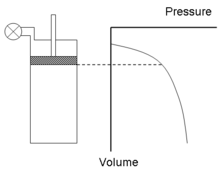
An indicator diagram is a chart used to estimate the performance of a steam engine. Specifically, an indicator chart records the pressure of steam versus the volume of steam in a cylinder, throughout a piston's cycle of motion in a steam engine. The indicator diagram enables calculation of the work performed and thus can provide a measure of the power produced by the engine.[1]
.jpg)
The indicator diagram was developed by James Watt and his employee John Southern (1758–1815) to improve the efficiency of engines. In 1796, Southern developed the simple, but critical, technique to generate the diagram by fixing a board so as to move with the piston, thereby tracing the "volume" axis, while a pencil, attached to a pressure gauge, moved at right angles to the piston, tracing "pressure".
The gauge enabled Watt to calculate the work done by the steam while ensuring that its pressure had dropped to zero by the end of the stroke, thereby ensuring that all useful energy had been extracted. The total work could be calculated from the area between the "volume" axis and the traced line. The latter fact had been realised by Davies Gilbert as early as 1792 and used by Jonathan Hornblower in litigation against Watt over patents on various designs. Daniel Bernoulli had also had the insight about how to calculate work.
Watt used the diagram to make radical improvements to steam engine performance and long kept it a trade secret. Though it was made public in a letter to the Quarterly Journal of Science in 1822,[2] it remained somewhat obscure, John Farey, Jr. only learning of it on seeing it used, probably by Watt's men, when he visited Russia in 1826.
In 1834, Émile Clapeyron used a diagram of pressure against volume to illustrate and elucidate the Carnot cycle, elevating it to a central position in the study of thermodynamics.[3]
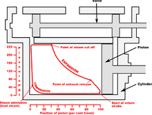
Later instruments (illus.) used paper wrapped around a cylindrical barrel with a pressure piston inside it, the rotation of the barrel coupled to the piston crosshead by a weight- or spring-tensioned wire.
.jpg)
References
- Richard L. Hills and A. J. Pacey (January 1972) "The measurement of power in early steam-driven textile mills," Technology and Culture, vol. 13, no. 1, pages 25–43.
- (Anonymous), "Account of a steam-engine indicator," Quarterly Journal of Science, vol. 13, page 95 (1822).
- Clapeyron, E. (1834) "Mémoire sur la puissance motrice de la chaleur" (Memoir on the motive power of heat), Journal de l'École Royale Polytechnique, vol. 14, no. 23, pages 153–190, 160–162.
Bibliography
- Cardwell, D.S.L. (1971). From Watt to Clausius: The Rise of Thermodynamics in the Early Industrial Age. Heinemann: London. pp. 79–81. ISBN 0-435-54150-1.
- Pacey, A.J. & Fisher, S.J. (1967) "Daniel Bernoulli and the vis viva of compressed air", The British Journal for the History of Science 3 (4), p. 388–392, doi:10.1017/S0007087400002934
- British Transport Commission (1957) Handbook for Railway Steam Locomotive Enginemen, London : B.T.C., p. 81, (facsimile copy publ. Ian Allan (1977), ISBN 0-7110-0628-8)
External links
- Walter, John. "The Engine Indicator. A collectors' guide to mechanical and optical/mechanical designs, 1800 to date". Canadian Museum of Making.
| Wikimedia Commons has media related to Indicator diagrams. |