Geodesy
Geodesy (/dʒiːˈɒdɪsi/)[1] is the Earth science of accurately measuring and understanding Earth's geometric shape, orientation in space and gravitational field.[2] The field also incorporates studies of how these properties change over time and equivalent measurements for other planets (known as planetary geodesy). Geodynamical phenomena include crustal motion, tides and polar motion, which can be studied by designing global and national control networks, applying space and terrestrial techniques and relying on datums and coordinate systems.
| Geodesy | ||||||||||||||||||||||||||
|---|---|---|---|---|---|---|---|---|---|---|---|---|---|---|---|---|---|---|---|---|---|---|---|---|---|---|
 | ||||||||||||||||||||||||||
|
Fundamentals |
||||||||||||||||||||||||||
|
Concepts |
||||||||||||||||||||||||||
|
Technologies
|
||||||||||||||||||||||||||
|
Standards (history)
|
||||||||||||||||||||||||||
Definition
The word geodesy comes from the Ancient Greek word γεωδαισία geodaisia (literally, "division of Earth").
It is primarily concerned with positioning within the temporally varying gravitational field. Geodesy in the German-speaking world is divided into "higher geodesy" ("Erdmessung" or "höhere Geodäsie"), which is concerned with measuring Earth on the global scale, and "practical geodesy" or "engineering geodesy" ("Ingenieurgeodäsie"), which is concerned with measuring specific parts or regions of Earth, and which includes surveying. Such geodetic operations are also applied to other astronomical bodies in the solar system. It is also the science of measuring and understanding Earth's geometric shape, orientation in space, and gravitational field.
To a large extent, the shape of Earth is the result of rotation, which causes its equatorial bulge, and the competition of geological processes such as the collision of plates and of volcanism, resisted by Earth's gravitational field. This applies to the solid surface, the liquid surface (dynamic sea surface topography) and Earth's atmosphere. For this reason, the study of Earth's gravitational field is called physical geodesy.
History
Geoid and reference ellipsoid
The geoid is essentially the figure of Earth abstracted from its topographical features. It is an idealized equilibrium surface of sea water, the mean sea level surface in the absence of currents and air pressure variations, and continued under the continental masses. The geoid, unlike the reference ellipsoid, is irregular and too complicated to serve as the computational surface on which to solve geometrical problems like point positioning. The geometrical separation between the geoid and the reference ellipsoid is called the geoidal undulation. It varies globally between ±110 m, when referred to the GRS 80 ellipsoid.
A reference ellipsoid, customarily chosen to be the same size (volume) as the geoid, is described by its semi-major axis (equatorial radius) a and flattening f. The quantity f = a − b/a, where b is the semi-minor axis (polar radius), is a purely geometrical one. The mechanical ellipticity of Earth (dynamical flattening, symbol J2) can be determined to high precision by observation of satellite orbit perturbations. Its relationship with the geometrical flattening is indirect. The relationship depends on the internal density distribution, or, in simplest terms, the degree of central concentration of mass.
The 1980 Geodetic Reference System (GRS 80) posited a 6,378,137 m semi-major axis and a 1:298.257 flattening. This system was adopted at the XVII General Assembly of the International Union of Geodesy and Geophysics (IUGG). It is essentially the basis for geodetic positioning by the Global Positioning System (GPS) and is thus also in widespread use outside the geodetic community. The numerous systems that countries have used to create maps and charts are becoming obsolete as countries increasingly move to global, geocentric reference systems using the GRS 80 reference ellipsoid.
The geoid is "realizable", meaning it can be consistently located on Earth by suitable simple measurements from physical objects like a tide gauge. The geoid can, therefore, be considered a real surface. The reference ellipsoid, however, has many possible instantiations and is not readily realizable, therefore it is an abstract surface. The third primary surface of geodetic interest—the topographic surface of Earth—is a realizable surface.
Coordinate systems in space
The locations of points in three-dimensional space are most conveniently described by three cartesian or rectangular coordinates, X, Y and Z. Since the advent of satellite positioning, such coordinate systems are typically geocentric: the Z-axis is aligned with Earth's (conventional or instantaneous) rotation axis.
Prior to the era of satellite geodesy, the coordinate systems associated with a geodetic datum attempted to be geocentric, but their origins differed from the geocenter by hundreds of meters, due to regional deviations in the direction of the plumbline (vertical). These regional geodetic data, such as ED 50 (European Datum 1950) or NAD 27 (North American Datum 1927) have ellipsoids associated with them that are regional "best fits" to the geoids within their areas of validity, minimizing the deflections of the vertical over these areas.
It is only because GPS satellites orbit about the geocenter, that this point becomes naturally the origin of a coordinate system defined by satellite geodetic means, as the satellite positions in space are themselves computed in such a system.
Geocentric coordinate systems used in geodesy can be divided naturally into two classes:
- Inertial reference systems, where the coordinate axes retain their orientation relative to the fixed stars, or equivalently, to the rotation axes of ideal gyroscopes; the X-axis points to the vernal equinox
- Co-rotating, also ECEF ("Earth Centred, Earth Fixed"), where the axes are attached to the solid body of Earth. The X-axis lies within the Greenwich observatory's meridian plane.
The coordinate transformation between these two systems is described to good approximation by (apparent) sidereal time, which takes into account variations in Earth's axial rotation (length-of-day variations). A more accurate description also takes polar motion into account, a phenomenon closely monitored by geodesists.
Coordinate systems in the plane

In surveying and mapping, important fields of application of geodesy, two general types of coordinate systems are used in the plane:
- Plano-polar, in which points in a plane are defined by a distance s from a specified point along a ray having a specified direction α with respect to a base line or axis;
- Rectangular, points are defined by distances from two perpendicular axes called x and y. It is geodetic practice—contrary to the mathematical convention—to let the x-axis point to the north and the y-axis to the east.
Rectangular coordinates in the plane can be used intuitively with respect to one's current location, in which case the x-axis will point to the local north. More formally, such coordinates can be obtained from three-dimensional coordinates using the artifice of a map projection. It is not possible to map the curved surface of Earth onto a flat map surface without deformation. The compromise most often chosen—called a conformal projection—preserves angles and length ratios, so that small circles are mapped as small circles and small squares as squares.
An example of such a projection is UTM (Universal Transverse Mercator). Within the map plane, we have rectangular coordinates x and y. In this case, the north direction used for reference is the map north, not the local north. The difference between the two is called meridian convergence.
It is easy enough to "translate" between polar and rectangular coordinates in the plane: let, as above, direction and distance be α and s respectively, then we have

The reverse transformation is given by:

Heights
In geodesy, point or terrain heights are "above sea level", an irregular, physically defined surface. Heights come in the following variants:
Each has its advantages and disadvantages. Both orthometric and normal heights are heights in metres above sea level, whereas geopotential numbers are measures of potential energy (unit: m2 s−2) and not metric. Orthometric and normal heights differ in the precise way in which mean sea level is conceptually continued under the continental masses. The reference surface for orthometric heights is the geoid, an equipotential surface approximating mean sea level.
None of these heights is in any way related to geodetic or ellipsoidial heights, which express the height of a point above the reference ellipsoid. Satellite positioning receivers typically provide ellipsoidal heights, unless they are fitted with special conversion software based on a model of the geoid.
Geodetic data
Because geodetic point coordinates (and heights) are always obtained in a system that has been constructed itself using real observations, geodesists introduce the concept of a "geodetic datum": a physical realization of a coordinate system used for describing point locations. The realization is the result of choosing conventional coordinate values for one or more datum points.
In the case of height data, it suffices to choose one datum point: the reference benchmark, typically a tide gauge at the shore. Thus we have vertical data like the NAP (Normaal Amsterdams Peil), the North American Vertical Datum 1988 (NAVD 88), the Kronstadt datum, the Trieste datum, and so on.
In case of plane or spatial coordinates, we typically need several datum points. A regional, ellipsoidal datum like ED 50 can be fixed by prescribing the undulation of the geoid and the deflection of the vertical in one datum point, in this case the Helmert Tower in Potsdam. However, an overdetermined ensemble of datum points can also be used.
Changing the coordinates of a point set referring to one datum, so to make them refer to another datum, is called a datum transformation. In the case of vertical data, this consists of simply adding a constant shift to all height values. In the case of plane or spatial coordinates, datum transformation takes the form of a similarity or Helmert transformation, consisting of a rotation and scaling operation in addition to a simple translation. In the plane, a Helmert transformation has four parameters; in space, seven.
- A note on terminology
In the abstract, a coordinate system as used in mathematics and geodesy is called a "coordinate system" in ISO terminology, whereas the International Earth Rotation and Reference Systems Service (IERS) uses the term "reference system". When these coordinates are realized by choosing datum points and fixing a geodetic datum, ISO says "coordinate reference system", while IERS says "reference frame". The ISO term for a datum transformation again is a "coordinate transformation".[3]
Point positioning
Point positioning is the determination of the coordinates of a point on land, at sea, or in space with respect to a coordinate system. Point position is solved by computation from measurements linking the known positions of terrestrial or extraterrestrial points with the unknown terrestrial position. This may involve transformations between or among astronomical and terrestrial coordinate systems. The known points used for point positioning can be triangulation points of a higher-order network or GPS satellites.
Traditionally, a hierarchy of networks has been built to allow point positioning within a country. Highest in the hierarchy were triangulation networks. These were densified into networks of traverses (polygons), into which local mapping surveying measurements, usually with measuring tape, corner prism, and the familiar red and white poles, are tied.
Nowadays all but special measurements (e.g., underground or high-precision engineering measurements) are performed with GPS. The higher-order networks are measured with static GPS, using differential measurement to determine vectors between terrestrial points. These vectors are then adjusted in traditional network fashion. A global polyhedron of permanently operating GPS stations under the auspices of the IERS is used to define a single global, geocentric reference frame which serves as the "zero order" global reference to which national measurements are attached.
For surveying mappings, frequently Real Time Kinematic GPS is employed, tying in the unknown points with known terrestrial points close by in real time.
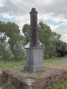
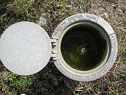
One purpose of point positioning is the provision of known points for mapping measurements, also known as (horizontal and vertical) control. In every country, thousands of such known points exist and are normally documented by national mapping agencies. Surveyors involved in real estate and insurance will use these to tie their local measurements.
Geodetic problems
In geometric geodesy, two standard problems exist—the first (direct or forward) and the second (inverse or reverse).
- First (direct or forward) geodetic problem
- Given a point (in terms of its coordinates) and the direction (azimuth) and distance from that point to a second point, determine (the coordinates of) that second point.
- Second (inverse or reverse) geodetic problem
- Given two points, determine the azimuth and length of the line (straight line, arc or geodesic) that connects them.
In plane geometry (valid for small areas on Earth's surface), the solutions to both problems reduce to simple trigonometry. On a sphere, however, the solution is significantly more complex, because in the inverse problem the azimuths will differ between the two end points of the connecting great circle, arc.
On the ellipsoid of revolution, geodesics may be written in terms of elliptic integrals, which are usually evaluated in terms of a series expansion—see, for example, Vincenty's formulae. In the general case, the solution is called the geodesic for the surface considered. The differential equations for the geodesic can be solved numerically.
Observational concepts
Here we define some basic observational concepts, like angles and coordinates, defined in geodesy (and astronomy as well), mostly from the viewpoint of the local observer.
- Plumbline or vertical: the direction of local gravity, or the line that results by following it.
- Zenith: the point on the celestial sphere where the direction of the gravity vector in a point, extended upwards, intersects it. It is more correct to call it a direction rather than a point.
- Nadir: the opposite point—or rather, direction—where the direction of gravity extended downward intersects the (obscured) celestial sphere.
- Celestial horizon: a plane perpendicular to a point's gravity vector.
- Azimuth: the direction angle within the plane of the horizon, typically counted clockwise from the north (in geodesy and astronomy) or the south (in France).
- Elevation: the angular height of an object above the horizon, Alternatively zenith distance, being equal to 90 degrees minus elevation.
- Local topocentric coordinates: azimuth (direction angle within the plane of the horizon), elevation angle (or zenith angle), distance.
- North celestial pole: the extension of Earth's (precessing and nutating) instantaneous spin axis extended northward to intersect the celestial sphere. (Similarly for the south celestial pole.)
- Celestial equator: the (instantaneous) intersection of Earth's equatorial plane with the celestial sphere.
- Meridian plane: any plane perpendicular to the celestial equator and containing the celestial poles.
- Local meridian: the plane containing the direction to the zenith and the direction to the celestial pole.
Measurements
The level is used for determining height differences and height reference systems, commonly referred to mean sea level. The traditional spirit level produces these practically most useful heights above sea level directly; the more economical use of GPS instruments for height determination requires precise knowledge of the figure of the geoid, as GPS only gives heights above the GRS80 reference ellipsoid. As geoid knowledge accumulates, one may expect the use of GPS heighting to spread.
The theodolite is used to measure horizontal and vertical angles to target points. These angles are referred to the local vertical. The tacheometer additionally determines, electronically or electro-optically, the distance to target, and is highly automated to even robotic in its operations. The method of free station position is widely used.
For local detail surveys, tacheometers are commonly employed although the old-fashioned rectangular technique using angle prism and steel tape is still an inexpensive alternative. Real-time kinematic (RTK) GPS techniques are used as well. Data collected are tagged and recorded digitally for entry into a Geographic Information System (GIS) database.
Geodetic GPS receivers produce directly three-dimensional coordinates in a geocentric coordinate frame. Such a frame is, e.g., WGS84, or the frames that are regularly produced and published by the International Earth Rotation and Reference Systems Service (IERS).
GPS receivers have almost completely replaced terrestrial instruments for large-scale base network surveys. For planet-wide geodetic surveys, previously impossible, we can still mention satellite laser ranging (SLR) and lunar laser ranging (LLR) and very-long-baseline interferometry (VLBI) techniques. All these techniques also serve to monitor irregularities in Earth's rotation as well as plate tectonic motions.
Gravity is measured using gravimeters, of which there are two kinds. First, "absolute gravimeters" are based on measuring the acceleration of free fall (e.g., of a reflecting prism in a vacuum tube). They are used to establish the vertical geospatial control and can be used in the field. Second, "relative gravimeters" are spring-based and are more common. They are used in gravity surveys over large areas for establishing the figure of the geoid over these areas. The most accurate relative gravimeters are called "superconducting" gravimeters, which are sensitive to one-thousandth of one-billionth of Earth-surface gravity. Twenty-some superconducting gravimeters are used worldwide for studying Earth's tides, rotation, interior, and ocean and atmospheric loading, as well as for verifying the Newtonian constant of gravitation.
In the future, gravity and altitude will be measured by relativistic time dilation measured by strontium optical clocks.
Units and measures on the ellipsoid
Geographical latitude and longitude are stated in the units degree, minute of arc, and second of arc. They are angles, not metric measures, and describe the direction of the local normal to the reference ellipsoid of revolution. This is approximately the same as the direction of the plumbline, i.e., local gravity, which is also the normal to the geoid surface. For this reason, astronomical position determination – measuring the direction of the plumbline by astronomical means – works fairly well provided an ellipsoidal model of the figure of Earth is used.
One geographical mile, defined as one minute of arc on the equator, equals 1,855.32571922 m. One nautical mile is one minute of astronomical latitude. The radius of curvature of the ellipsoid varies with latitude, being the longest at the pole and the shortest at the equator as is the nautical mile.
A metre was originally defined as the 10-millionth part of the length from equator to North Pole along the meridian through Paris (the target was not quite reached in actual implementation, so that is off by 200 ppm in the current definitions). This means that one kilometre is roughly equal to (1/40,000) * 360 * 60 meridional minutes of arc, which equals 0.54 nautical mile, though this is not exact because the two units are defined on different bases (the international nautical mile is defined as exactly 1,852 m, corresponding to a rounding of 1,000/0.54 m to four digits).
Temporal change
In geodesy, temporal change can be studied by a variety of techniques. Points on Earth's surface change their location due to a variety of mechanisms:
- Continental plate motion, plate tectonics
- Episodic motion of tectonic origin, especially close to fault lines
- Periodic effects due to tides
- Postglacial land uplift due to isostatic adjustment
- Mass variations due to hydrological changes
- Anthropogenic movements such as reservoir construction or petroleum or water extraction
The science of studying deformations and motions of Earth's crust and its solidity as a whole is called geodynamics. Often, study of Earth's irregular rotation is also included in its definition.
Techniques for studying geodynamic phenomena on the global scale include:
- Satellite positioning by GPS
- Very-long-baseline interferometry (VLBI)
- Satellite and lunar laser ranging
- Regionally and locally precise levelling
- Precise tacheometers
- Monitoring of gravity change
- Interferometric synthetic aperture radar (InSAR) using satellite images
Notable geodesists
Mathematical geodesists before 1900
- Pythagoras 580–490 BC, ancient Greece[4]
- Eratosthenes 276–194 BC, ancient Greece
- Hipparchus c. 190–120 BC, ancient Greece
- Posidonius c. 135–51 BC, ancient Greece
- Claudius Ptolemy c. AD 83–168, Roman Empire (Roman Egypt)
- Al-Ma'mun 786–833, Baghdad (Iraq/Mesopotamia)
- Abu Rayhan Biruni 973–1048, Khorasan (Iran/Samanid Dynasty)
- Muhammad al-Idrisi 1100–1166, (Arabia & Sicily)
- Regiomontanus 1436–1476, (Germany/Austria)
- Abel Foullon 1513–1563 or 1565, (France)
- Pedro Nunes 1502–1578 (Portugal)
- Gerhard Mercator 1512–1594 (Belgium & Germany)
- Snellius (Willebrord Snel van Royen) 1580–1626, Leiden (Netherlands)
- Christiaan Huygens 1629–1695 (Netherlands)
- Pierre Bouguer 1698–1758, (France & Peru)
- Pierre de Maupertuis 1698–1759 (France)
- Alexis Clairaut 1713–1765 (France)
- Johann Heinrich Lambert 1728–1777 (France)
- Roger Joseph Boscovich 1711–1787, (Rome/ Berlin/ Paris)
- Ino Tadataka 1745–1818, (Tokyo)
- Georg von Reichenbach 1771–1826, Bavaria (Germany)
- Pierre-Simon Laplace 1749–1827, Paris (France)
- Adrien Marie Legendre 1752–1833, Paris (France)
- Johann Georg von Soldner 1776–1833, Munich (Germany)
- George Everest 1790–1866 (England and India)
- Friedrich Wilhelm Bessel 1784–1846, Königsberg (Germany)
- Heinrich Christian Schumacher 1780–1850 (Germany & Russian Empire)
- Carl Friedrich Gauss 1777–1855, Göttingen (Germany)
- Friedrich Georg Wilhelm Struve 1793–1864, Dorpat and Pulkovo (Russian Empire)
- J. H. Pratt 1809–1871, London (England)
- Friedrich H. C. Paschen 1804–1873, Schwerin (Germany)
- Johann Benedikt Listing 1808–1882 (Germany)
- Johann Jacob Baeyer 1794–1885, Berlin (Germany)
- Sir George Biddell Airy 1801–1892, Cambridge & London
- Karl Maximilian von Bauernfeind 1818–1894, Munich (Germany)
- Wilhelm Jordan 1842–1899, (Germany)
- Hervé Faye 1814–1902 (France)
- George Gabriel Stokes 1819–1903 (England)
- Carlos Ibáñez e Ibáñez de Ibero 1825–1891, Barcelona (Spain)
- Henri Poincaré 1854–1912, Paris (France)
- Alexander Ross Clarke 1828–1914, London (England)
- Charles Sanders Peirce 1839–1914 (United States)
- Friedrich Robert Helmert 1843–1917, Potsdam (Germany)
- Heinrich Bruns 1848–1919, Berlin (Germany)
- Loránd Eötvös 1848–1919 (Hungary)
20th century geodesists
- John Fillmore Hayford, 1868–1925, (US)
- Feodosy Nikolaevich Krasovsky, 1878–1948, (Russian Empire, USSR)
- Alfred Wegener, 1880–1930, (Germany and Greenland)
- William Bowie, 1872–1940, (US)
- Friedrich Hopfner, 1881–1949, Vienna, (Austria)
- Tadeusz Banachiewicz, 1882–1954, (Poland)
- Felix Andries Vening-Meinesz, 1887–1966, (Netherlands)
- Martin Hotine, 1898–1968, (England)
- Yrjö Väisälä, 1889–1971, (Finland)
- Veikko Aleksanteri Heiskanen, 1895–1971, (Finland and US)
- Karl Ramsayer, 1911–1982, Stuttgart, (Germany)
- Buckminster Fuller, 1895–1983 (United States)
- Harold Jeffreys, 1891–1989, London, (England)
- Reino Antero Hirvonen, 1908–1989, (Finland)
- Mikhail Sergeevich Molodenskii, 1909–1991, (Russia)
- Maria Ivanovna Yurkina, 1923–2010, (Russia)
- Guy Bomford, 1899–1996, (India?)[5]
- Antonio Marussi, 1908–1984, (Italy)
- Hellmut Schmid, 1914–1998, (Switzerland)
- William M. Kaula, 1926–2000, Los Angeles, (US)
- John A. O'Keefe, 1916–2000, (US)
- Thaddeus Vincenty, 1920–2002, (Poland)
- Willem Baarda, 1917–2005, (Netherlands)
- Irene Kaminka Fischer, 1907–2009, (US)
- Arne Bjerhammar, 1917–2011, (Sweden)
- Karl-Rudolf Koch 1935, Bonn, (Germany)
- Helmut Moritz, 1933, Graz, (Austria)
- Petr Vaníček, 1935, Fredericton, (Canada)
- Erik Grafarend, 1939, Stuttgart, (Germany)
- Hans-Georg Wenzel (1949–1999), (Germany)
- Floyd Hough, 1898–1976, (US)
Unlisted
See also
- Fundamentals
- Governmental agencies
- U.S. National Geodetic Survey
- National Geospatial-Intelligence Agency
- United States Geological Survey
- International organizations
- International Association of Geodesy
- International Federation of Surveyors
- International Geodetic Student Organisation
- Other
References
- "geodesy | Definition of geodesy in English by Lexico Dictionaries". Lexico Dictionaries | English. Retrieved 2019-08-15.
- "What Is Geodesy". National Ocean Service. Retrieved 8 February 2018.
- (ISO 19111: Spatial referencing by coordinates).
- "DEFENSE MAPPING AGENCY TECHNICAL REPORT 80-003". Ngs.noaa.gov. Retrieved 8 December 2018.
- "Guy Bomford tribute". Bomford.net. Retrieved 8 December 2018.
Further reading
- F. R. Helmert, Mathematical and Physical Theories of Higher Geodesy, Part 1, ACIC (St. Louis, 1964). This is an English translation of Die mathematischen und physikalischen Theorieen der höheren Geodäsie, Vol 1 (Teubner, Leipzig, 1880).
- F. R. Helmert, Mathematical and Physical Theories of Higher Geodesy, Part 2, ACIC (St. Louis, 1964). This is an English translation of Die mathematischen und physikalischen Theorieen der höheren Geodäsie, Vol 2 (Teubner, Leipzig, 1884).
- B. Hofmann-Wellenhof and H. Moritz, Physical Geodesy, Springer-Verlag Wien, 2005. (This text is an updated edition of the 1967 classic by W.A. Heiskanen and H. Moritz).
- W. Kaula, Theory of Satellite Geodesy : Applications of Satellites to Geodesy, Dover Publications, 2000. (This text is a reprint of the 1966 classic).
- Vaníček P. and E.J. Krakiwsky, Geodesy: the Concepts, pp. 714, Elsevier, 1986.
- Torge, W (2001), Geodesy (3rd edition), published by de Gruyter, ISBN 3-11-017072-8.
- Thomas H. Meyer, Daniel R. Roman, and David B. Zilkoski. "What does height really mean?" (This is a series of four articles published in Surveying and Land Information Science, SaLIS.)
- "Part I: Introduction" SaLIS Vol. 64, No. 4, pages 223–233, December 2004.
- "Part II: Physics and gravity" SaLIS Vol. 65, No. 1, pages 5–15, March 2005.
- "Part III: Height systems" SaLIS Vol. 66, No. 2, pages 149–160, June 2006.
- "Part IV: GPS heighting" SaLIS Vol. 66, No. 3, pages 165–183, September 2006.
External links
![]()
![]()
- Geodetic awareness guidance note, Geodesy Subcommittee, Geomatics Committee, International Association of Oil & Gas Producers
- . Encyclopædia Britannica. 11 (11th ed.). 1911. pp. 607–615.
| Overviews |  | |
|---|---|---|
| History of geology | ||
| Сomposition and structure | ||
| Historical geology | ||
| Motion | ||
| Water | ||
| Geophysics | ||
| Applications | ||
| Occupations | ||
| ||
| Authority control |
|
|---|