Gas chromatography
Gas chromatography (GC) is a common type of chromatography used in analytical chemistry for separating and analyzing compounds that can be vaporized without decomposition. Typical uses of GC include testing the purity of a particular substance, or separating the different components of a mixture (the relative amounts of such components can also be determined). In some situations, GC may help in identifying a compound. In preparative chromatography, GC can be used to prepare pure compounds from a mixture.[1][2]
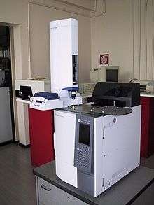 A gas chromatograph with a headspace sampler | |
| Acronym | GC |
|---|---|
| Classification | Chromatography |
| Analytes | Organic Inorganic Must be volatile |
| Other techniques | |
| Related | Thin layer chromatography High performance liquid chromatography |
| Hyphenated | Gas chromatography-mass spectrometry |
In gas chromatography, the mobile phase (or "moving phase") is a carrier gas, usually an inert gas such as helium or an unreactive gas such as nitrogen. Helium remains the most commonly used carrier gas in about 90% of instruments although hydrogen is preferred for improved separations.[3] The stationary phase is a microscopic layer of liquid or polymer on an inert solid support, inside a piece of glass or metal tubing called a column (a homage to the fractionating column used in distillation). The instrument used to perform gas chromatography is called a gas chromatograph (or "aerograph", "gas separator").
The gaseous compounds being analyzed interact with the walls of the column, which is coated with a stationary phase. This causes each compound to elute at a different time, known as the retention time of the compound. The comparison of retention times is what gives GC its analytical usefulness.
Gas chromatography is in principle similar to column chromatography (as well as other forms of chromatography, such as HPLC, TLC), but has several notable differences. First, the process of separating the compounds in a mixture is carried out between a liquid stationary phase and a gas mobile phase, whereas in column chromatography the stationary phase is a solid and the mobile phase is a liquid. (Hence the full name of the procedure is "Gas–liquid chromatography", referring to the mobile and stationary phases, respectively.) Second, the column through which the gas phase passes is located in an oven where the temperature of the gas can be controlled, whereas column chromatography (typically) has no such temperature control. Finally, the concentration of a compound in the gas phase is solely a function of the vapor pressure of the gas.[1]
Gas chromatography is also sometimes known as vapor-phase chromatography (VPC), or gas–liquid partition chromatography (GLPC). These alternative names, as well as their respective abbreviations, are frequently used in scientific literature. Strictly speaking, GLPC is the most correct terminology, and is thus preferred by many authors.[1]
History
Chromatography dates to 1903 in the work of the Russian scientist, Mikhail Semenovich Tswett,[4] who separated plant pigments via liquid column chromatography. German physical chemist Erika Cremer in 1947 together with Austrian graduate student Fritz Prior developed the theoretical foundations of GC and built the first liquid-gas chromatograph, but her work was deemed irrelevant and was ignored for a long time.[5] Archer John Porter Martin, who was awarded the Nobel Prize for his work in developing liquid–liquid (1941) and paper (1944) chromatography, is therefore credited for the foundation of gas chromatography. The popularity of gas chromatography quickly rose after the development of the flame ionization detector.[6]
GC analysis
A gas chromatograph is a chemical analysis instrument for separating chemicals in a complex sample. A gas chromatograph uses a flow-through narrow tube known as the column, through which different chemical constituents of a sample pass in a gas stream (carrier gas, mobile phase) at different rates depending on their various chemical and physical properties and their interaction with a specific column filling, called the stationary phase. As the chemicals exit the end of the column, they are detected and identified electronically. The function of the stationary phase in the column is to separate different components, causing each one to exit the column at a different time (retention time). Other parameters that can be used to alter the order or time of retention are the carrier gas flow rate, column length and the temperature.
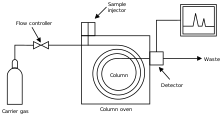
In a GC analysis, a known volume of gaseous or liquid analyte is injected into the "entrance" (head) of the column, usually using a microsyringe (or, solid phase microextraction fibers, or a gas source switching system). As the carrier gas sweeps the analyte molecules through the column, this motion is inhibited by the adsorption of the analyte molecules either onto the column walls or onto packing materials in the column. The rate at which the molecules progress along the column depends on the strength of adsorption, which in turn depends on the type of molecule and on the stationary phase materials. Since each type of molecule has a different rate of progression, the various components of the analyte mixture are separated as they progress along the column and reach the end of the column at different times (retention time). A detector is used to monitor the outlet stream from the column; thus, the time at which each component reaches the outlet and the amount of that component can be determined. Generally, substances are identified (qualitatively) by the order in which they emerge (elute) from the column and by the retention time of the analyte in the column.
Physical components
Autosamplers
The autosampler provides the means to introduce a sample automatically into the inlets. Manual insertion of the sample is possible but is no longer common. Automatic insertion provides better reproducibility and time-optimization.
Different kinds of autosamplers exist. Autosamplers can be classified in relation to sample capacity (auto-injectors vs. autosamplers, where auto-injectors can work a small number of samples), to robotic technologies (XYZ robot[7] vs. rotating robot – the most common), or to analysis:
- Liquid
- Static head-space by syringe technology
- Dynamic head-space by transfer-line technology
- Solid phase microextraction (SPME)
Inlets
The column inlet (or injector) provides the means to introduce a sample into a continuous flow of carrier gas. The inlet is a piece of hardware attached to the column head.
Common inlet types are:
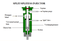
- S/SL (split/splitless) injector; a sample is introduced into a heated small chamber via a syringe through a septum – the heat facilitates volatilization of the sample and sample matrix. The carrier gas then either sweeps the entirety (splitless mode) or a portion (split mode) of the sample into the column. In split mode, a part of the sample/carrier gas mixture in the injection chamber is exhausted through the split vent. Split injection is preferred when working with samples with high analyte concentrations (>0.1%) whereas splitless injection is best suited for trace analysis with low amounts of analytes (<0.01%). In splitless mode the split valve opens after a pre-set amount of time to purge heavier elements that would otherwise contaminate the system. This pre-set (splitless) time should be optimized, the shorter time (e.g., 0.2 min) ensures less tailing but loss in response, the longer time (2 min) increases tailing but also signal.[8]
- On-column inlet; the sample is here introduced directly into the column in its entirety without heat, or at a temperature below the boiling point of the solvent. The low temperature condenses the sample into a narrow zone. The column and inlet can then be heated, releasing the sample into the gas phase. This ensures the lowest possible temperature for chromatography and keeps samples from decomposing above their boiling point.
- PTV injector; Temperature-programmed sample introduction was first described by Vogt in 1979. Originally Vogt developed the technique as a method for the introduction of large sample volumes (up to 250 µL) in capillary GC. Vogt introduced the sample into the liner at a controlled injection rate. The temperature of the liner was chosen slightly below the boiling point of the solvent. The low-boiling solvent was continuously evaporated and vented through the split line. Based on this technique, Poy developed the programmed temperature vaporising injector; PTV. By introducing the sample at a low initial liner temperature many of the disadvantages of the classic hot injection techniques could be circumvented.
- Gas source inlet or gas switching valve; gaseous samples in collection bottles are connected to what is most commonly a six-port switching valve. The carrier gas flow is not interrupted while a sample can be expanded into a previously evacuated sample loop. Upon switching, the contents of the sample loop are inserted into the carrier gas stream.
- P/T (Purge-and-Trap) system; An inert gas is bubbled through an aqueous sample causing insoluble volatile chemicals to be purged from the matrix. The volatiles are 'trapped' on an absorbent column (known as a trap or concentrator) at ambient temperature. The trap is then heated and the volatiles are directed into the carrier gas stream. Samples requiring preconcentration or purification can be introduced via such a system, usually hooked up to the S/SL port.
The choice of carrier gas (mobile phase) is important. Hydrogen has a range of flow rates that are comparable to helium in efficiency. However, helium may be more efficient and provide the best separation if flow rates are optimized. Helium is non-flammable and works with a greater number of detectors and older instruments. Therefore, helium is the most common carrier gas used. However, the price of helium has gone up considerably over recent years, causing an increasing number of chromatographers to switch to hydrogen gas. Historical use, rather than rational consideration, may contribute to the continued preferential use of helium.
Detectors
The most commonly used detectors are the flame ionization detector (FID) and the thermal conductivity detector (TCD). Both are sensitive to a wide range of components, and both work over a wide range of concentrations. While TCDs are essentially universal and can be used to detect any component other than the carrier gas (as long as their thermal conductivities are different from that of the carrier gas, at detector temperature), FIDs are sensitive primarily to hydrocarbons, and are more sensitive to them than TCD. However, a FID cannot detect water. Both detectors are also quite robust. Since TCD is non-destructive, it can be operated in-series before a FID (destructive), thus providing complementary detection of the same analytes.[9] Other detectors are sensitive only to specific types of substances, or work well only in narrower ranges of concentrations.
Thermal conductivity detector (TCD) relies on the thermal conductivity of matter passing around a tungsten -rhenium filament with a current traveling through it.[10] In this set up helium or nitrogen serve as the carrier gas because of their relatively high thermal conductivity which keep the filament cool and maintain uniform resistivity and electrical efficiency of the filament.[10][11] However, when analyte molecules elute from the column, mixed with carrier gas, the thermal conductivity decreases and this causes a detector response.[11] The response is due to the decreased thermal conductivity causing an increase in filament temperature and resistivity resulting in fluctuations in voltage.[10] Detector sensitivity is proportional to filament current while it is inversely proportional to the immediate environmental temperature of that detector as well as flow rate of the carrier gas.[10]
In a flame ionization detector (FID), electrodes are placed adjacent to a flame fueled by hydrogen / air near the exit of the column, and when carbon containing compounds exit the column they are pyrolyzed by the flame.[10][11] This detector works only for organic / hydrocarbon containing compounds due to the ability of the carbons to form cations and electrons upon pyrolysis which generates a current between the electrodes.[10][11] The increase in current is translated and appears as a peak in a chromatogram. FIDs have low detection limits (a few picograms per second) but they are unable to generate ions from carbonyl containing carbons.[10] FID compatible carrier gasses include helium, hydrogen, nitrogen, and argon.[10][11]
Alkali flame detector (AFD) or alkali flame ionization detector (AFID) has high sensitivity to nitrogen and phosphorus, similar to NPD. However, the alkaline metal ions are supplied with the hydrogen gas, rather than a bead above the flame. For this reason AFD does not suffer the "fatigue" of the NPD, but provides a constant sensitivity over long period of time. In addition, when alkali ions are not added to the flame, AFD operates like a standard FID. A catalytic combustion detector (CCD) measures combustible hydrocarbons and hydrogen. Discharge ionization detector (DID) uses a high-voltage electric discharge to produce ions.
The polyarc reactor is an add-on to new or existing GC-FID instruments that converts all organic compounds to methane molecules prior to their detection by the FID. This technique can be used to improve the response of the FID and allow for the detection of many more carbon-containing compounds.[12] The complete conversion of compounds to methane and the now equivalent response in the detector also eliminates the need for calibrations and standards because response factors are all equivalent to those of methane. This allows for the rapid analysis of complex mixtures that contain molecules where standards are not available.
Flame photometric detector (FPD) uses a photomultiplier tube to detect spectral lines of the compounds as they are burned in a flame. Compounds eluting off the column are carried into a hydrogen fueled flame which excites specific elements in the molecules, and the excited elements (P,S, Halogens, Some Metals) emit light of specific characteristic wavelengths.[11] The emitted light is filtered and detected by a photomultiplier tube.[10][11] In particular, phosphorus emission is around 510–536 nm and sulfur emission is at 394 nm.[10][11] With an atomic emission detector (AED), a sample eluting from a column enters a chamber which is energized by microwaves that induce a plasma.[11] The plasma causes the analyte sample to decompose and certain elements generate an atomic emission spectra.[11] The atomic emission spectra is diffracted by a diffraction grating and detected by a series of photomultiplier tubes or photo diodes.[11]
Electron capture detector (ECD) uses a radioactive beta particle (electron) source to measure the degree of electron capture. ECD are used for the detection of molecules containing electronegative / withdrawing elements and functional groups like halogens, carbonyl, nitriles, nitro groups, and organometalics.[10][11] In this type of detector either nitrogen or 5% methane in argon is used as the mobile phase carrier gas.[10][11] The carrier gas passes between two electrodes placed at the end of the column, and adjacent to the cathode (negative electrode) resides a radioactive foil such as 63Ni.[10][11] The radioactive foil emits a beta particle (electron) which collides with and ionizes the carrier gas to generate more ions resulting in a current.[10][11] When analyte molecules with electronegative / withdrawing elements or functional groups electrons are captured which results in a decrease in current generating a detector response.[10][11]
Nitrogen–phosphorus detector (NPD), a form of thermionic detector where nitrogen and phosphorus alter the work function on a specially coated bead and a resulting current is measured.
Dry electrolytic conductivity detector (DELCD) uses an air phase and high temperature (v. Coulsen) to measure chlorinated compounds.
Mass spectrometer (MS), also called GC-MS; highly effective and sensitive, even in a small quantity of sample. This detector can be used to identify the analytes in chromatograms by their mass spectrum.[13] Some GC-MS are connected to an NMR spectrometer which acts as a backup detector. This combination is known as GC-MS-NMR. Some GC-MS-NMR are connected to an infrared spectrophotometer which acts as a backup detector. This combination is known as GC-MS-NMR-IR. It must, however, be stressed this is very rare as most analyses needed can be concluded via purely GC-MS.
Vacuum ultraviolet (VUV) represents the most recent development in gas chromatography detectors. Most chemical species absorb and have unique gas phase absorption cross sections in the approximately 120–240 nm VUV wavelength range monitored. Where absorption cross sections are known for analytes, the VUV detector is capable of absolute determination (without calibration) of the number of molecules present in the flow cell in the absence of chemical interferences.[14]
Other detectors include the Hall electrolytic conductivity detector (ElCD), helium ionization detector (HID), infrared detector (IRD), photo-ionization detector (PID), pulsed discharge ionization detector (PDD), and thermionic ionization detector (TID).[15]
Methods
The method is the collection of conditions in which the GC operates for a given analysis. Method development is the process of determining what conditions are adequate and/or ideal for the analysis required.
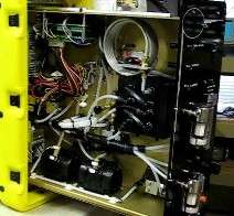
Conditions which can be varied to accommodate a required analysis include inlet temperature, detector temperature, column temperature and temperature program, carrier gas and carrier gas flow rates, the column's stationary phase, diameter and length, inlet type and flow rates, sample size and injection technique. Depending on the detector(s) (see below) installed on the GC, there may be a number of detector conditions that can also be varied. Some GCs also include valves which can change the route of sample and carrier flow. The timing of the opening and closing of these valves can be important to method development.
Carrier gas selection and flow rates
Typical carrier gases include helium, nitrogen, argon, hydrogen and air. Which gas to use is usually determined by the detector being used, for example, a DID requires helium as the carrier gas. When analyzing gas samples, however, the carrier is sometimes selected based on the sample's matrix, for example, when analyzing a mixture in argon, an argon carrier is preferred, because the argon in the sample does not show up on the chromatogram. Safety and availability can also influence carrier selection, for example, hydrogen is flammable, and high-purity helium can be difficult to obtain in some areas of the world. (See: Helium—occurrence and production.) As a result of helium becoming more scarce, hydrogen is often being substituted for helium as a carrier gas in several applications.
The purity of the carrier gas is also frequently determined by the detector, though the level of sensitivity needed can also play a significant role. Typically, purities of 99.995% or higher are used. The most common purity grades required by modern instruments for the majority of sensitivities are 5.0 grades, or 99.999% pure meaning that there is a total of 10 ppm of impurities in the carrier gas that could affect the results. The highest purity grades in common use are 6.0 grades, but the need for detection at very low levels in some forensic and environmental applications has driven the need for carrier gases at 7.0 grade purity and these are now commercially available. Trade names for typical purities include "Zero Grade," "Ultra-High Purity (UHP) Grade," "4.5 Grade" and "5.0 Grade."
The carrier gas linear velocity affects the analysis in the same way that temperature does (see above). The higher the linear velocity the faster the analysis, but the lower the separation between analytes. Selecting the linear velocity is therefore the same compromise between the level of separation and length of analysis as selecting the column temperature. The linear velocity will be implemented by means of the carrier gas flow rate, with regards to the inner diameter of the column.
With GCs made before the 1990s, carrier flow rate was controlled indirectly by controlling the carrier inlet pressure, or "column head pressure." The actual flow rate was measured at the outlet of the column or the detector with an electronic flow meter, or a bubble flow meter, and could be an involved, time consuming, and frustrating process. It was not possible to vary the pressure setting during the run, and thus the flow was essentially constant during the analysis. The relation between flow rate and inlet pressure is calculated with Poiseuille's equation for compressible fluids.
Many modern GCs, however, electronically measure the flow rate, and electronically control the carrier gas pressure to set the flow rate. Consequently, carrier pressures and flow rates can be adjusted during the run, creating pressure/flow programs similar to temperature programs.
Stationary compound selection
The polarity of the solute is crucial for the choice of stationary compound, which in an optimal case would have a similar polarity as the solute. Common stationary phases in open tubular columns are cyanopropylphenyl dimethyl polysiloxane, carbowax polyethyleneglycol, biscyanopropyl cyanopropylphenyl polysiloxane and diphenyl dimethyl polysiloxane. For packed columns more options are available.[10]
Inlet types and flow rates
The choice of inlet type and injection technique depends on if the sample is in liquid, gas, adsorbed, or solid form, and on whether a solvent matrix is present that has to be vaporized. Dissolved samples can be introduced directly onto the column via a COC injector, if the conditions are well known; if a solvent matrix has to be vaporized and partially removed, a S/SL injector is used (most common injection technique); gaseous samples (e.g., air cylinders) are usually injected using a gas switching valve system; adsorbed samples (e.g., on adsorbent tubes) are introduced using either an external (on-line or off-line) desorption apparatus such as a purge-and-trap system, or are desorbed in the injector (SPME applications).
Sample size and injection technique
Sample injection
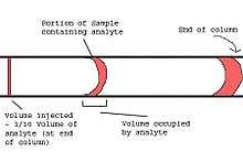
The real chromatographic analysis starts with the introduction of the sample onto the column. The development of capillary gas chromatography resulted in many practical problems with the injection technique. The technique of on-column injection, often used with packed columns, is usually not possible with capillary columns. In the injection system in the capillary gas chromatograph the amount injected should not overload the column and the width of the injected plug should be small compared to the spreading due to the chromatographic process. Failure to comply with this latter requirement will reduce the separation capability of the column. As a general rule, the volume injected, Vinj, and the volume of the detector cell, Vdet, should be about 1/10 of the volume occupied by the portion of sample containing the molecules of interest (analytes) when they exit the column.
Some general requirements which a good injection technique should fulfill are that it should be possible to obtain the column's optimum separation efficiency, it should allow accurate and reproducible injections of small amounts of representative samples, it should induce no change in sample composition, it should not exhibit discrimination based on differences in boiling point, polarity, concentration or thermal/catalytic stability, and it should be applicable for trace analysis as well as for undiluted samples.
However, there are a number of problems inherent in the use of syringes for injection. Even the best syringes claim an accuracy of only 3%, and in unskilled hands, errors are much larger. The needle may cut small pieces of rubber from the septum as it injects sample through it. These can block the needle and prevent the syringe filling the next time it is used. It may not be obvious that this has happened. A fraction of the sample may get trapped in the rubber, to be released during subsequent injections. This can give rise to ghost peaks in the chromatogram. There may be selective loss of the more volatile components of the sample by evaporation from the tip of the needle.[16]
Column selection
The choice of column depends on the sample and the active measured. The main chemical attribute regarded when choosing a column is the polarity of the mixture, but functional groups can play a large part in column selection. The polarity of the sample must closely match the polarity of the column stationary phase to increase resolution and separation while reducing run time. The separation and run time also depends on the film thickness (of the stationary phase), the column diameter and the column length.
Column temperature and temperature program
The column(s) in a GC are contained in an oven, the temperature of which is precisely controlled electronically. (When discussing the "temperature of the column," an analyst is technically referring to the temperature of the column oven. The distinction, however, is not important and will not subsequently be made in this article.)
The rate at which a sample passes through the column is directly proportional to the temperature of the column. The higher the column temperature, the faster the sample moves through the column. However, the faster a sample moves through the column, the less it interacts with the stationary phase, and the less the analytes are separated.
In general, the column temperature is selected to compromise between the length of the analysis and the level of separation.
A method which holds the column at the same temperature for the entire analysis is called "isothermal." Most methods, however, increase the column temperature during the analysis, the initial temperature, rate of temperature increase (the temperature "ramp"), and final temperature are called the temperature program.
A temperature program allows analytes that elute early in the analysis to separate adequately, while shortening the time it takes for late-eluting analytes to pass through the column.
Data reduction and analysis
Qualitative analysis
Generally, chromatographic data is presented as a graph of detector response (y-axis) against retention time (x-axis), which is called a chromatogram. This provides a spectrum of peaks for a sample representing the analytes present in a sample eluting from the column at different times. Retention time can be used to identify analytes if the method conditions are constant. Also, the pattern of peaks will be constant for a sample under constant conditions and can identify complex mixtures of analytes. However, in most modern applications, the GC is connected to a mass spectrometer or similar detector that is capable of identifying the analytes represented by the peaks.
Quantitative analysis
The area under a peak is proportional to the amount of analyte present in the chromatogram. By calculating the area of the peak using the mathematical function of integration, the concentration of an analyte in the original sample can be determined. Concentration can be calculated using a calibration curve created by finding the response for a series of concentrations of analyte, or by determining the relative response factor of an analyte. The relative response factor is the expected ratio of an analyte to an internal standard (or external standard) and is calculated by finding the response of a known amount of analyte and a constant amount of internal standard (a chemical added to the sample at a constant concentration, with a distinct retention time to the analyte).
In most modern GC-MS systems, computer software is used to draw and integrate peaks, and match MS spectra to library spectra.
Applications
In general, substances that vaporize below 300 °C (and therefore are stable up to that temperature) can be measured quantitatively. The samples are also required to be salt-free; they should not contain ions. Very minute amounts of a substance can be measured, but it is often required that the sample must be measured in comparison to a sample containing the pure, suspected substance known as a reference standard.
Various temperature programs can be used to make the readings more meaningful; for example to differentiate between substances that behave similarly during the GC process.
Professionals working with GC analyze the content of a chemical product, for example in assuring the quality of products in the chemical industry; or measuring toxic substances in soil, air or water. GC is very accurate if used properly and can measure picomoles of a substance in a 1 ml liquid sample, or parts-per-billion concentrations in gaseous samples.
In practical courses at colleges, students sometimes get acquainted to the GC by studying the contents of Lavender oil or measuring the ethylene that is secreted by Nicotiana benthamiana plants after artificially injuring their leaves. These GC analyse hydrocarbons (C2-C40+). In a typical experiment, a packed column is used to separate the light gases, which are then detected with a TCD. The hydrocarbons are separated using a capillary column and detected with a FID. A complication with light gas analyses that include H2 is that He, which is the most common and most sensitive inert carrier (sensitivity is proportional to molecular mass) has an almost identical thermal conductivity to hydrogen (it is the difference in thermal conductivity between two separate filaments in a Wheatstone Bridge type arrangement that shows when a component has been eluted). For this reason, dual TCD instruments used with a separate channel for hydrogen that uses nitrogen as a carrier are common. Argon is often used when analysing gas phase chemistry reactions such as F-T synthesis so that a single carrier gas can be used rather than two separate ones. The sensitivity is reduced, but this is a trade off for simplicity in the gas supply.
Gas chromatography is used extensively in forensic science. Disciplines as diverse as solid drug dose (pre-consumption form) identification and quantification, arson investigation, paint chip analysis, and toxicology cases, employ GC to identify and quantify various biological specimens and crime-scene evidence.
In popular culture
Movies, books and TV shows tend to misrepresent the capabilities of gas chromatography and the work done with these instruments.
In the United States' TV show CSI, for example, GCs are used to rapidly identify unknown samples. For example, an analyst may say fifteen minutes after receiving the sample: "This is gasoline bought at a Chevron station in the past two weeks."
In fact, a typical GC analysis takes much more time; sometimes a single sample must be run more than an hour according to the chosen program; and even more time is needed to "heat out" the column so it is free from the first sample and can be used for the next. Equally, several runs are needed to confirm the results of a study – a GC analysis of a single sample may simply yield a result per chance (see statistical significance).
Also, GC does not positively identify most samples; and not all substances in a sample will necessarily be detected. All a GC truly tells you is at which relative time a component eluted from the column and that the detector was sensitive to it. To make results meaningful, analysts need to know which components at which concentrations are to be expected; and even then a small amount of a substance can hide itself behind a substance having both a higher concentration and the same relative elution time. Last but not least the results of the sample must often be checked against a GC analysis of a reference sample containing only the suspected substance.
A GC-MS can remove much of this ambiguity, since the mass spectrometer will identify the component's molecular weight. But this still takes time and skill to do properly.
Similarly, most GC analyses are not push-button operations. You cannot simply drop a sample vial into an auto-sampler's tray, push a button and have a computer tell you everything you need to know about the sample. The operating program must be carefully chosen according to the expected sample composition.
A push-button operation can exist for running similar samples repeatedly, such as in a chemical production environment or for comparing 20 samples from the same experiment to calculate the mean content of the same substance. However, for the kind of investigative work portrayed in books, movies and TV shows, this is clearly not the case.
The gas chromatograph and it’s inventor Archer Martin was briefly mentioned in The Simpsons Season 3, Episode 9 “Flaming Moe’s” in a show-and-tell in Bart’s class.
See also
- Analytical chemistry
- Chromatography
- Gas chromatography–mass spectrometry
- High-performance liquid chromatography
- Inverse gas chromatography
- Standard addition
- Thin layer chromatography
- Unresolved complex mixture
- Secondary electrospray ionization
- Proton transfer reaction mass spectrometry
- Selected ion flow tube mass spectrometry
References
- Pavia, L., Gary M. Lampman, George S. Kritz, Randall G. Engel (2006). Introduction to Organic Laboratory Techniques (4th Ed.). Thomson Brooks/Cole. pp. 797–817. ISBN 978-0-495-28069-9.CS1 maint: multiple names: authors list (link)
- "Gas Chromatography". Linde AG. Archived from the original on 3 March 2012. Retrieved 11 March 2012.
- Grob, Konrad (1997). "Carrier Gases for GC". Restek Advantage, Restek Corporation. Retrieved March 9, 2016.
- "Berichte der Deutschen Botanischen Gesellschaft v.24 1906". HathiTrust. Retrieved 2019-04-19.
- Ettre, Leslie S. (2008), The Beginnings of Gas Adsorption Chromatography 60 Years Ago, LCGC North America
- R. A. Dewar; McWILLIAM, I. G. (March 1958). "Flame Ionization Detector for Gas Chromatography". Nature. 181 (4611): 760. Bibcode:1958Natur.181..760M. doi:10.1038/181760a0. ISSN 1476-4687.
- Carvalho, Matheus (2018). "Osmar, the open-source microsyringe autosampler". HardwareX. 3: 10–38. doi:10.1016/j.ohx.2018.01.001.
- Chasteen, Thomas G. "Split/Splitless and On-Column Gas Chromatographic Injectors". Retrieved October 6, 2019.
- "Gas Chromatography". ACRF. Retrieved 11 March 2012.
- Harris, Daniel C. (1999). "24. Gas Chromatography". Quantitative chemical analysis (Chapter) (Fifth ed.). W. H. Freeman and Company. pp. 675–712. ISBN 978-0-7167-2881-8.
- Higson, S. (2004). Analytical Chemistry. OXFORD University Press ISBN 978-0-19-850289-0
- Dauenhauer, Paul (January 21, 2015). "Quantitative carbon detector (QCD) for calibration-free, high-resolution characterization of complex mixtures". Lab Chip. 15 (2): 440–7. doi:10.1039/c4lc01180e. PMID 25387003.
- Skoog, Douglas A.; West, Donald M.; James Holler, F.; Crouch, Stanley R. (2013-01-01). Fundamentals of analytical chemistry. Skoog, Douglas A.,, West, Donald M.,, Holler, F. James,, Crouch, Stanley R. (Ninth ed.). Belmont, CA. ISBN 9780495558286. OCLC 824171785.
- Schug, Kevin A.; Sawicki, Ian; Carlton, Doug D.; Fan, Hui; McNair, Harold M.; Nimmo, John P.; Kroll, Peter; Smuts, Jonathan; Walsh, Phillip; Harrison, Dale (1834). "Vacuum Ultraviolet Detector for Gas Chromatography". Analytical Chemistry. 86 (16): 8329–35. doi:10.1021/ac5018343. PMID 25079505.
- "Ionization-based detectors for gas chromatography". Journal of Chromatography A. 1421: 137–153. 2015-11-20. doi:10.1016/j.chroma.2015.02.061.
- Grob, Robert L.; Barry, Eugene F. (2004). Modern Practice of Gas Chromatography (4th Ed.). John Wiley & Sons. ISBN 978-0-471-22983-4.
External links
![]()
- Chromatographic Columns in the Chemistry LibreTexts Library
- Gas Chromatography at Curlie
| Instrumentation |
|
|---|---|
| Techniques |
|
| Sampling |
|
| Calibration | |
| Prominent publications | |
| |