Electrical cable
An electrical cable is an assembly of one or more wires running side by side or bundled, which is used to carry electric current.


A cable assembly is the composition of one or more electrical cables and their corresponding connectors.[1] A cable assembly is not necessarily suitable for connecting two devices but can be a partial product (e.g. to be soldered onto a printed circuit board with a connector mounted to the housing). Cable assemblies can also take the form of a cable tree or cable harness, used to connect many terminals together.
Etymology
The term cable originally referred to a nautical line of specific length where multiple ropes are combined to produce a strong thick line that was used to anchor large ships. As electric technology developed, people changed from using bare copper wire to using groupings of wires and various sheathing and shackling methods that resembled the mechanical cabling so the term was adopted for electrical wiring. In the 19th century and early 20th century, electrical cable was often insulated using cloth, rubber or paper. Plastic materials are generally used today, except for high-reliability power cables. The term has also come to be associated with communications because of its use in electrical communications.
Modern applications

Electrical cables are used to connect two or more devices, enabling the transfer of electrical signals or power from one device to the other. Cables are used for a wide range of purposes, and each must be tailored for that purpose. Cables are used extensively in electronic devices for power and signal circuits. Long-distance communication takes place over undersea cables. Power cables are used for bulk transmission of alternating and direct current power, especially using high-voltage cable. Electrical cables are extensively used in building wiring for lighting, power and control circuits permanently installed in buildings. Since all the circuit conductors required can be installed in a cable at one time, installation labor is saved compared to certain other wiring methods.
Physically, an electrical cable is an assembly consisting of one or more conductors with their own insulations and optional screens, individual covering(s), assembly protection and protective covering(s). Electrical cables may be made more flexible by stranding the wires. In this process, smaller individual wires are twisted or braided together to produce larger wires that are more flexible than solid wires of similar size. Bunching small wires before concentric stranding adds the most flexibility. Copper wires in a cable may be bare, or they may be plated with a thin layer of another metal, most often tin but sometimes gold, silver or some other material. Tin, gold, and silver are much less prone to oxidation than copper, which may lengthen wire life, and makes soldering easier. Tinning is also used to provide lubrication between strands. Tinning was used to help removal of rubber insulation. Tight lays during stranding makes the cable extensible (CBA – as in telephone handset cords).
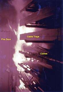
Cables can be securely fastened and organized, such as by using trunking, cable trays, cable ties or cable lacing. Continuous-flex or flexible cables used in moving applications within cable carriers can be secured using strain relief devices or cable ties.
At high frequencies, current tends to run along the surface of the conductor. This is known as the skin effect.
Cables and electromagnetic fields
Any current-carrying conductor, including a cable, radiates an electromagnetic field. Likewise, any conductor or cable will pick up energy from any existing electromagnetic field around it. These effects are often undesirable, in the first case amounting to unwanted transmission of energy which may adversely affect nearby equipment or other parts of the same piece of equipment; and in the second case, unwanted pickup of noise which may mask the desired signal being carried by the cable, or, if the cable is carrying power supply or control voltages, pollute them to such an extent as to cause equipment malfunction.
The first solution to these problems is to keep cable lengths in buildings short since pick up and transmission are essentially proportional to the length of the cable. The second solution is to route cables away from trouble. Beyond this, there are particular cable designs that minimize electromagnetic pickup and transmission. Three of the principal design techniques are shielding, coaxial geometry, and twisted-pair geometry.
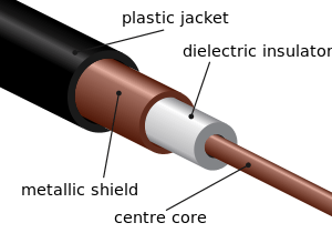
Shielding makes use of the electrical principle of the Faraday cage. The cable is encased for its entire length in foil or wire mesh. All wires running inside this shielding layer will be to a large extent decoupled from external electrical fields, particularly if the shield is connected to a point of constant voltage, such as earth or ground. Simple shielding of this type is not greatly effective against low-frequency magnetic fields, however - such as magnetic "hum" from a nearby power transformer. A grounded shield on cables operating at 2.5 kV or more gathers leakage current and capacitive current, protecting people from electric shock and equalizing stress on the cable insulation.
Coaxial design helps to further reduce low-frequency magnetic transmission and pickup. In this design the foil or mesh shield has a circular cross section and the inner conductor is exactly at its center. This causes the voltages induced by a magnetic field between the shield and the core conductor to consist of two nearly equal magnitudes which cancel each other.
A twisted pair has two wires of a cable twisted around each other. This can be demonstrated by putting one end of a pair of wires in a hand drill and turning while maintaining moderate tension on the line. Where the interfering signal has a wavelength that is long compared to the pitch of the twisted pair, alternate lengths of wires develop opposing voltages, tending to cancel the effect of the interference.
Fire protection
In building construction, electrical cable jacket material is a potential source of fuel for fires. To limit the spread of fire, one may use cable coating materials or jacketing that is fire retardant. The plastic covering on some metal clad cables may be stripped off at installation to reduce the fuel source for fires. Inorganic coatings and boxes around cables safeguard the adjacent areas from the fire threat associated with unprotected cable jacketing. However, this fire protection also traps heat generated from conductor losses, so the protection must be thin.
To provide fire protection to a cable, the insulation is treated with fire retardant materials, or non-combustible mineral insulation is used .
Types
- Coaxial cable – used for radio frequency signals, for example in cable television distribution systems.
- Direct-buried cable
- Flexible cables
- Filled cable
- Heliax cable
- Non-metallic sheathed cable (or nonmetallic building wire, NM, NM-B)[2]
- Metallic sheathed cable (or armored cable, AC, or BX)[2]
- Multicore cable (consist of more than one wire and is covered by cable jacket)
- Paired cable – Composed of two individually insulated conductors that are usually used in DC or low-frequency AC applications
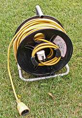
- Portable cord – Flexible cable for AC power in portable applications
- Ribbon cable – Useful when many wires are required. This type of cable can easily flex, and it is designed to handle low-level voltages.
- Shielded cable – Used for sensitive electronic circuits or to provide protection in high-voltage applications.
- Single cable (from time to time this name is used for wire)
- Structured cabling
- Submersible cable
- Twin and earth
- Twinax cable
- Twin-lead – This type of cable is a flat two-wire line. It is commonly called a 300 Ω line because the line has an impedance of 300 Ω. It is often used as a transmission line between an antenna and a receiver (e.g., TV and radio). These cables are stranded to lower skin effects.
- Twisted pair – Consists of two interwound insulated wires. It resembles a paired cable, except that the paired wires are twisted
Codes and colours
CENELEC HD 361 is a ratified standard published by CENELEC, which relates to wire and cable marking type, whose goal is to harmonize cables. Deutsches Institut für Normung (DIN, VDE) has released a similar standard (DIN VDE 0292).
Hybrid cables
Hybrid optical and electrical cables can be used in wireless outdoor fiber-to-the-antenna (FTTA) applications. In these cables, the optical fibers carry information, and the electrical conductors are used to transmit power. These cables can be placed in several environments to serve antennas mounted on poles, towers or other structures. Local safety regulations may apply.
See also
- American wire gauge
- Cable dressing
- Cable gland
- Cable harness
- Cable knitting
- Cable length
- Cable management
- Cable modem
- Cable reel
- Cable television
- Category 5 cable
- Category 6 cable
- Category 7 cable
- Circuit integrity
- Cross-linked polyethylene
- Electrical connector
- Extension cable
- International Cablemakers Federation
- Over/under cable coiling
- Polyvinyl chloride
- Portable cord
- Power cable
- Profibus
- Submarine communications cable
- Submarine power cable
- Steel Wire Armoured (SWA) Cable
- SY control cable
- Tensile structure
- Transmission line
- Underwriter's knot
References
- "What Is a Cable Assembly?". wiseGEEK. Retrieved 1 July 2019.
- "Electrical Wiring FAQ (Part 2 of 2)Section - What is Romex/NM/NMD? What is BX? When should I use each?". faqs.org.
Further reading
- R. M. Black, The History of Electric Wires and Cables, Peter Pergrinus, London 1983 ISBN 0-86341-001-4
- BICC Cables Ltd, "Electric Cables Handbook", WileyBlackwell; London 3rd Edition 1997, ISBN 0-632-04075-0
External links
| Look up cable in Wiktionary, the free dictionary. |
| Wikimedia Commons has media related to Electric cables. |