Diffraction grating
In optics, a diffraction grating is an optical component with a periodic structure that splits and diffracts light into several beams travelling in different directions. The emerging coloration is a form of structural coloration.[1][2] The directions of these beams depend on the spacing of the grating and the wavelength of the light so that the grating acts as the dispersive element. Because of this, gratings are commonly used in monochromators and spectrometers.
For practical applications, gratings generally have ridges or rulings on their surface rather than dark lines.[3] Such gratings can be either transmissive or reflective. Gratings that modulate the phase rather than the amplitude of the incident light are also produced, frequently using holography.[4]
The principles of diffraction gratings were discovered by James Gregory, about a year after Newton's prism experiments, initially with items such as bird feathers.[5] The first man-made diffraction grating was made around 1785 by Philadelphia inventor David Rittenhouse, who strung hairs between two finely threaded screws.[6][7] This was similar to notable German physicist Joseph von Fraunhofer's wire diffraction grating in 1821.[8][9] Gratings with the lowest line-distance (d) were created, in the 1860s, by Friedrich Adolph Nobert (1806–1881) in Greifswald;[10] then the two Americans Lewis Morris Rutherfurd (1816–1892) and William B. Rogers (1804–1882) took over the lead;[11][12] and, by the end of the 19th century, the concave gratings of Henry Augustus Rowland (1848–1901) were the best available.[13][14]
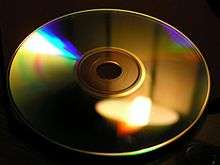
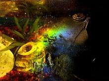
Diffraction can create "rainbow" colors when illuminated by a wide-spectrum (e.g., continuous) light source. The sparkling effects from the closely spaced narrow tracks on optical storage disks such as CDs or DVDs are an example, while the similar rainbow effects caused by thin layers of oil (or gasoline, etc.) on water are not caused by a grating but rather by interference effects in reflections from the closely spaced transmissive layers (see examples, below). A grating has parallel lines, while a CD has a spiral of finely spaced data tracks. Diffraction colors also appear when one looks at a bright point source through a translucent fine-pitch umbrella-fabric covering. Decorative patterned plastic films based on reflective grating patches are very inexpensive and commonplace.
Theory of operation
The relationship between the grating spacing and the angles of the incident and diffracted beams of light is known as the grating equation. According to the Huygens–Fresnel principle, each point on the wavefront of a propagating wave can be considered to act as a point source, and the wavefront at any subsequent point can be found by adding together the contributions from each of these individual point sources. Gratings may be of the 'reflective' or 'transmissive' type, analogous to a mirror or lens, respectively. A grating has a 'zero-order mode' (where m = 0), in which there is no diffraction and a ray of light behaves according to the laws of reflection and refraction the same as with a mirror or lens, respectively.
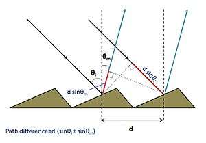
An idealised grating is made up of a set of slits of spacing d, that must be wider than the wavelength of interest to cause diffraction. Assuming a plane wave of monochromatic light of wavelength λ with normal incidence (perpendicular to the grating), each slit in the grating acts as a quasi point-source from which light propagates in all directions (although this is typically limited to a hemisphere). After light interacts with the grating, the diffracted light is composed of the sum of interfering wave components emanating from each slit in the grating. At any given point in space through which diffracted light may pass, the path length to each slit in the grating varies. Since path length varies, generally, so do the phases of the waves at that point from each of the slits. Thus, they add or subtract from each other to create peaks and valleys through additive and destructive interference. When the path difference between the light from adjacent slits is equal to half the wavelength, λ/2, the waves are out of phase, and thus cancel each other to create points of minimum intensity. Similarly, when the path difference is λ, the phases add together and maxima occur. The maxima occur at angles θm, which satisfy the relationship d sinθm/λ = | m |, where θm is the angle between the diffracted ray and the grating's normal vector, and d is the distance from the center of one slit to the center of the adjacent slit, and m is an integer representing the propagation-mode of interest.
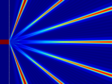
Thus, when light is normally incident on the grating, the diffracted light has maxima at angles θm given by:

It is straightforward to show that if a plane wave is incident at any arbitrary angle θi, the grating equation becomes:

When solved for the diffracted angle maxima, the equation is:

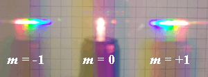
Please note that these equations assume that both sides of the grating are in contact with the same medium (e.g. air). The light that corresponds to direct transmission (or specular reflection in the case of a reflection grating) is called the zero order, and is denoted m = 0. The other maxima occur at angles represented by non-zero integers m. Note that m can be positive or negative, resulting in diffracted orders on both sides of the zero order beam.
This derivation of the grating equation is based on an idealised grating. However, the relationship between the angles of the diffracted beams, the grating spacing and the wavelength of the light apply to any regular structure of the same spacing, because the phase relationship between light scattered from adjacent elements of the grating remains the same. The detailed distribution of the diffracted light depends on the detailed structure of the grating elements as well as on the number of elements in the grating, but it always gives maxima in the directions given by the grating equation.
Gratings can be made in which various properties of the incident light are modulated in a periodic pattern; these include
- transparency (transmission amplitude diffraction gratings);
- reflectance (reflection amplitude diffraction gratings);
- refractive index or optical path length (phase diffraction gratings);
- direction of optical axis (optical axis diffraction gratings).
The grating equation applies in all these cases.
Quantum electrodynamics
Quantum electrodynamics (QED) offers another derivation of the properties of a diffraction grating in terms of photons as particles (at some level). QED can be described intuitively with the path integral formulation of quantum mechanics. As such it can model photons as potentially following all paths from a source to a final point, each path with a certain probability amplitude. These probability amplitudes can be represented as a complex number or equivalent vector—or, as Richard Feynman simply calls them in his book on QED, "arrows".
For the probability that a certain event will happen, one sums the probability amplitudes for all of the possible ways in which the event can occur, and then takes the square of the length of the result. The probability amplitude for a photon from a monochromatic source to arrive at a certain final point at a given time, in this case, can be modeled as an arrow that spins rapidly until it is evaluated when the photon reaches its final point. For example, for the probability that a photon will reflect off of a mirror and be observed at a given point a given amount of time later, one sets the photon's probability amplitude spinning as it leaves the source, follows it to the mirror, and then to its final point, even for paths that do not involve bouncing off of the mirror at equal angles. One can then evaluate the probability amplitude at the photon's final point; next, one can integrate over all of these arrows (see vector sum), and square the length of the result to obtain the probability that this photon will reflect off of the mirror in the pertinent fashion. The times these paths take are what determine the angle of the probability amplitude arrow, as they can be said to "spin" at a constant rate (which is related to the frequency of the photon).
The times of the paths near the classical reflection site of the mirror are nearly the same, so the probability amplitudes point in nearly the same direction—thus, they have a sizable sum. Examining the paths towards the edges of the mirror reveals that the times of nearby paths are quite different from each other, and thus we wind up summing vectors that cancel out quickly. So, there is a higher probability that light will follow a near-classical reflection path than a path further out. However, a diffraction grating can be made out of this mirror, by scraping away areas near the edge of the mirror that usually cancel nearby amplitudes out—but now, since the photons don't reflect from the scraped-off portions, the probability amplitudes that would all point, for instance, at forty-five degrees, can have a sizable sum. Thus, this lets light of the right frequency sum to a larger probability amplitude, and as such possess a larger probability of reaching the appropriate final point.
This particular description involves many simplifications: a point source, a "surface" that light can reflect off of (thus neglecting the interactions with electrons) and so forth. The biggest simplification is perhaps in the fact that the "spinning" of the probability amplitude arrows is actually more accurately explained as a "spinning" of the source, as the probability amplitudes of photons do not "spin" while they are in transit. We obtain the same variation in probability amplitudes by letting the time at which the photon left the source be indeterminate—and the time of the path now tells us when the photon would have left the source, and thus what the angle of its "arrow" would be. However, this model and approximation is a reasonable one to illustrate a diffraction grating conceptually. Light of a different frequency may also reflect off of the same diffraction grating, but with a different final point.[15]
Gratings as dispersive elements
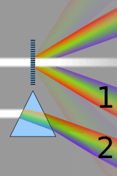
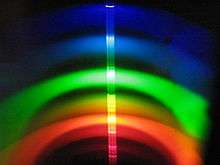
The wavelength dependence in the grating equation shows that the grating separates an incident polychromatic beam into its constituent wavelength components, i.e., it is dispersive. Each wavelength of input beam spectrum is sent into a different direction, producing a rainbow of colors under white light illumination. This is visually similar to the operation of a prism, although the mechanism is very different.
The diffracted beams corresponding to consecutive orders may overlap, depending on the spectral content of the incident beam and the grating density. The higher the spectral order, the greater the overlap into the next order.
The grating equation shows that the angles of the diffracted orders only depend on the grooves' period, and not on their shape. By controlling the cross-sectional profile of the grooves, it is possible to concentrate most of the diffracted energy in a particular order for a given wavelength. A triangular profile is commonly used. This technique is called blazing. The incident angle and wavelength for which the diffraction is most efficient are often called blazing angle and blazing wavelength. The efficiency of a grating may also depend on the polarization of the incident light. Gratings are usually designated by their groove density, the number of grooves per unit length, usually expressed in grooves per millimeter (g/mm), also equal to the inverse of the groove period. The groove period must be on the order of the wavelength of interest; the spectral range covered by a grating is dependent on groove spacing and is the same for ruled and holographic gratings with the same grating constant. The maximum wavelength that a grating can diffract is equal to twice the grating period, in which case the incident and diffracted light are at ninety degrees to the grating normal. To obtain frequency dispersion over a wider frequency one must use a prism. In the optical regime, in which the use of gratings is most common, this corresponds to wavelengths between 100 nm and 10 µm. In that case, the groove density can vary from a few tens of grooves per millimeter, as in echelle gratings, to a few thousands of grooves per millimeter.
When groove spacing is less than half the wavelength of light, the only present order is the m = 0 order. Gratings with such small periodicity are called subwavelength gratings and exhibit special optical properties. Made on an isotropic material the subwavelength gratings give rise to form birefringence, in which the material behaves as if it were birefringent.
Fabrication
Originally, high-resolution gratings were ruled by high-quality ruling engines whose construction was a large undertaking. Henry Joseph Grayson designed a machine to make diffraction gratings, succeeding with one of 120,000 lines to the inch (approx. 4,724 lines per mm) in 1899. Later, photolithographic techniques created gratings from a holographic interference pattern. Holographic gratings have sinusoidal grooves and may not be as efficient as ruled gratings, but are often preferred in monochromators because they produce less stray light. A copying technique can make high quality replicas from master gratings of either type, thereby lowering fabrication costs.
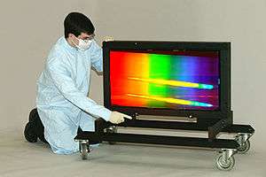
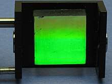
Another method for manufacturing diffraction gratings uses a photosensitive gel sandwiched between two substrates. A holographic interference pattern exposes the gel, which is later developed. These gratings, called volume phase holography diffraction gratings (or VPH diffraction gratings) have no physical grooves, but instead a periodic modulation of the refractive index within the gel. This removes much of the surface scattering effects typically seen in other types of gratings. These gratings also tend to have higher efficiencies, and allow for the inclusion of complicated patterns into a single grating. In older versions of such gratings, environmental susceptibility was a trade-off, as the gel had to be contained at low temperature and humidity. Typically, the photosensitive substances are sealed between two substrates that make them resistant to humidity, and thermal and mechanical stresses. VPH diffraction gratings are not destroyed by accidental touches and are more scratch resistant than typical relief gratings.
Semiconductor technology today is also utilized to etch holographically patterned gratings into robust materials such as fused silica. In this way, low stray-light holography is combined with the high efficiency of deep, etched transmission gratings, and can be incorporated into high volume, low cost semiconductor manufacturing technology.
A new technology for grating insertion into integrated photonic lightwave circuits is digital planar holography (DPH). DPH gratings are generated in computer and fabricated on one or several interfaces of an optical waveguide planar with standard micro-lithography or nano-imprinting methods, compatible with mass-production. Light propagates inside the DPH gratings, confined by the refractive index gradient, which provides longer interaction path and greater flexibility in light steering.
Examples
Diffraction gratings are often used in monochromators, spectrometers, lasers, wavelength division multiplexing devices, optical pulse compressing devices, and many other optical instruments.
Ordinary pressed CD and DVD media are every-day examples of diffraction gratings and can be used to demonstrate the effect by reflecting sunlight off them onto a white wall. This is a side effect of their manufacture, as one surface of a CD has many small pits in the plastic, arranged in a spiral; that surface has a thin layer of metal applied to make the pits more visible. The structure of a DVD is optically similar, although it may have more than one pitted surface, and all pitted surfaces are inside the disc.[16][17]
Due to the sensitivity to the refractive index of the media, diffraction grating can be used as sensor of fluid properties.[18]
In a standard pressed vinyl record when viewed from a low angle perpendicular to the grooves, a similar but less defined effect to that in a CD/DVD is seen. This is due to viewing angle (less than the critical angle of reflection of the black vinyl) and the path of the light being reflected due to this being changed by the grooves, leaving a rainbow relief pattern behind.
Diffraction gratings are also used to distribute evenly the frontlight of e-readers such as the Nook Simple Touch with GlowLight.[19]
Gratings from electronic components
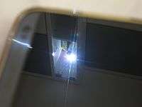
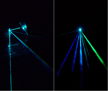
Some everyday electronic components contain fine and regular patterns, and as a result readily serve as diffraction gratings. For example, CCD sensors from discarded mobile phones and cameras can be removed from the device. With a laser pointer, diffraction can reveal the spatial structure of the CCD sensors.[20] This can be done for LCD or LED displays of smart phones as well. Because such displays are usually protected just by transparent casing, experiments can be done without damaging the phones. If accurate measurements are not intended, a spotlight can reveal the diffraction patterns.
Natural gratings
Striated muscle is the most commonly found natural diffraction grating[21] and, this has helped physiologists in determining the structure of such muscle. Aside from this, the chemical structure of crystals can be thought of as diffraction gratings for types of electromagnetic radiation other than visible light, this is the basis for techniques such as X-ray crystallography.
Most commonly confused with diffraction gratings are the iridescent colors of peacock feathers, mother-of-pearl, and butterfly wings. Iridescence in birds,[22] fish[23] and insects[22][24] is often caused by thin-film interference rather than a diffraction grating. Diffraction produces the entire spectrum of colors as the viewing angle changes, whereas thin-film interference usually produces a much narrower range. The surfaces of flowers can also create a diffraction, but the cell structures in plants are usually too irregular to produce the fine slit geometry necessary for a diffraction grating.[25] The iridescence signal of flowers is thus only appreciable very locally and hence not visible to man and flower visiting insects.[26][27] However, natural gratings do occur in some invertebrate animals, like the peacock spiders[28], the antennae of seed shrimp, and have even been discovered in Burgess Shale fossils.[29][30]
Diffraction grating effects are sometimes seen in meteorology. Diffraction coronas are colorful rings surrounding a source of light, such as the sun. These are usually observed much closer to the light source than halos, and are caused by very fine particles, like water droplets, ice crystals, or smoke particles in a hazy sky. When the particles are all nearly the same size they diffract the incoming light at very specific angles. The exact angle depends on the size of the particles. Diffraction coronas are commonly observed around light sources, like candle flames or street lights, in the fog. Cloud iridescence is caused by diffraction, occurring along coronal rings when the particles in the clouds are all uniform in size.[31]
See also
- Angle-sensitive pixel
- Blazed grating
- Diffraction efficiency
- Diffraction spike
- Echelle grating
- Fraunhofer diffraction
- Fraunhofer diffraction (mathematics)
- Fresnel diffraction
- Grism
- Henry Augustus Rowland
- Kapitza-Dirac effect
- Kirchhoff's diffraction formula
- N-slit interferometric equation
- Ultrasonic grating
- Virtually imaged phased array
- Zone plate
Notes
- Srinivasarao, M. (1999). "Nano-Optics in the Biological World: Beetles, Butterflies, Birds, and Moths". Chemical Reviews. 99 (7): 1935–1962. doi:10.1021/cr970080y. PMID 11849015.
- Kinoshita, S.; Yoshioka, S.; Miyazaki, J. (2008). "Physics of structural colors". Reports on Progress in Physics. 71 (7): 076401. Bibcode:2008RPPh...71g6401K. doi:10.1088/0034-4885/71/7/076401.
- "Introduction to Diffraction Grating" (PDF). Thor Labs. Retrieved 30 April 2020.
- AK Yetisen; H Butt; F da Cruz Vasconcellos; Y Montelongo; CAB Davidson; J Blyth; JB Carmody; S Vignolini; U Steiner; JJ Baumberg; TD Wilkinson; CR Lowe (2013). "Light-Directed Writing of Chemically Tunable Narrow-Band Holographic Sensors". Advanced Optical Materials. 2 (3): 250–254. doi:10.1002/adom.201300375.
- Letter from James Gregory to John Collins, dated 13 May 1673. Reprinted in: Rigaud, Stephen Jordan, ed. (1841). Correspondence of Scientific Men of the Seventeenth Century …. 2. Oxford University Press. pp. 251–5. especially p. 254
- Hopkinson, F.; Rittenhouse, David (1786). "An optical problem, proposed by Mr. Hopkinson, and solved by Mr. Rittenhouse". Transactions of the American Philosophical Society. 2: 201–6. doi:10.2307/1005186. JSTOR 1005186.
- Thomas D. Cope (1932) "The Rittenhouse diffraction grating". Reprinted in: Rittenhouse, David (1980). Hindle, Brooke (ed.). The Scientific Writings of David Rittenhouse. Arno Press. pp. 377–382. Bibcode:1980swdr.book.....R. ISBN 9780405125683. (A reproduction of Rittenhouse's letter re his diffraction grating appears on pp. 369–374.)
- Fraunhofer, Joseph von (1821). "Neue Modifikation des Lichtes durch gegenseitige Einwirkung und Beugung der Strahlen, und Gesetze derselben" [New modification of light by the mutual influence and the diffraction of [light] rays, and the laws thereof]. Denkschriften der Königlichen Akademie der Wissenschaften zu München (Memoirs of the Royal Academy of Science in Munich). 8: 3–76.
- Fraunhofer, Joseph von (1823). "Kurzer Bericht von den Resultaten neuerer Versuche über die Gesetze des Lichtes, und die Theorie derselben" [Short account of the results of new experiments on the laws of light, and the theory thereof]. Annalen der Physik. 74 (8): 337–378. Bibcode:1823AnP....74..337F. doi:10.1002/andp.18230740802.
- Turner, G. L'E. (1967). "The contributions to Science of Friedrich Adolph Nobert". Bulletin of the Institute of Physics and the Physical Society. 18 (10): 338–348. doi:10.1088/0031-9112/18/10/006.
- Warner, Deborah J. (1971). "Lewis M. Rutherfurd: Pioneer Astronomical Photographer and Spectroscopist". Technology and Culture. 12 (2): 190–216. doi:10.2307/3102525. JSTOR 3102525.
- Warner, Deborah J. (1988). The Michelson Era in American Science 1870-1930. New York: American Institute of Physics. pp. 2–12.
- Hentschel, Klaus (1993). "The Discovery of the Redshift of Solar Fraunhofer Lines by Rowland and Jewell in Baltimore around 1890" (PDF). Historical Studies in the Physical and Biological Sciences. 23 (2): 219–277. doi:10.2307/27757699. JSTOR 27757699.
- Sweeetnam, George (2000). The Command of Light: Rowland's School of Physics and the Spectrum. Philadelphia: American Philosophical Society. ISBN 978-08716-923-82.
- Feynman, Richard (1985). QED: The Strange Theory of Light and Matter. Princeton University Press. ISBN 978-0691083889.
- Ambient Diagnostics by Yang Cai -- CRC Press 2014 Page 267
- http://www.nnin.org/sites/default/files/files/Karen_Rama_USING_CDs_AND_DVDs_AS_DIFFRACTION_GRATINGS_0.pdf
- Xu, Zhida; Han, Kevin; Khan, Ibrahim; Wang, Xinhao; Liu, Logan (2014). "Liquid refractive index sensing independent of opacity using an optofluidic diffraction sensor". Optics Letters. 39 (20): 6082–6085. arXiv:1410.0903. Bibcode:2014OptL...39.6082X. doi:10.1364/OL.39.006082. PMID 25361161.
- "Step 17". Nook Simple Touch with GlowLight Teardown. iFixit. 2012.
- Barreiro, Jesús J.; Pons, Amparo; Barreiro, Juan C.; Castro-Palacio, Juan C.; Monsoriu, Juan A. (March 2014). "Diffraction by electronic components of everyday use" (PDF). American Journal of Physics. 82 (3): 257–261. Bibcode:2014AmJPh..82..257B. doi:10.1119/1.4830043. hdl:10251/54288.
- Baskin, R.J.; Roos, K.P.; Yeh, Y. (October 1979). "Light diffraction study of single skeletal muscle fibers". Biophys. J. 28 (1): 45–64. Bibcode:1979BpJ....28...45B. doi:10.1016/S0006-3495(79)85158-9. PMC 1328609. PMID 318066.
- Stavenga, D. G. (2014). "Thin Film and Multilayer Optics Cause Structural Colors of Many Insects and Birds". Materials Today: Proceedings. 1: 109–121. doi:10.1016/j.matpr.2014.09.007.
- Roberts, N. W.; Marshall, N. J.; Cronin, T. W. (2012). "High levels of reflectivity and pointillist structural color in fish, cephalopods, and beetles". Proceedings of the National Academy of Sciences. 109 (50): E3387. Bibcode:2012PNAS..109E3387R. doi:10.1073/pnas.1216282109. PMC 3528518. PMID 23132935.
- Stavenga, D. G.; Leertouwer, H. L.; Wilts, B. D. (2014). "Coloration principles of nymphaline butterflies - thin films, melanin, ommochromes and wing scale stacking". Journal of Experimental Biology. 217 (12): 2171–2180. doi:10.1242/jeb.098673. PMID 24675561.
- Van Der Kooi, C. J.; Wilts, B. D.; Leertouwer, H. L.; Staal, M.; Elzenga, J. T. M.; Stavenga, D. G. (2014). "Iridescent flowers? Contribution of surface structures to optical signaling" (PDF). New Phytologist. 203 (2): 667–73. doi:10.1111/nph.12808. PMID 24713039.
- Lee, David W. (2007). Nature's Palette: The Science of Plant Color. University of Chicago Press. pp. 255–6. ISBN 978-0-226-47105-1.CS1 maint: ref=harv (link)
- Van Der Kooi, C. J.; Dyer, A. G.; Stavenga, D. G. (2015). "Is floral iridescence a biologically relevant cue in plant-pollinator signaling?" (PDF). New Phytologist. 205 (1): 18–20. doi:10.1111/nph.13066. PMID 25243861.
- Hsiung, Bor-Kai; Siddique, Radwanul Hasan; Stavenga, Doekele G.; Otto, Jürgen C.; Allen, Michael C.; Liu, Ying; Lu, Yong-Feng; Deheyn, Dimitri D.; Shawkey, Matthew D. (2017-12-22). "Rainbow peacock spiders inspire miniature super-iridescent optics". Nature Communications. 8 (1): 2278. Bibcode:2017NatCo...8.2278H. doi:10.1038/s41467-017-02451-x. ISSN 2041-1723. PMC 5741626. PMID 29273708.
- Lee 2007, p. 41
- "Colouring in the fossil past". News. Natural History Museum. 15 March 2006. Archived from the original on 12 August 2010. Retrieved 14 September 2010.
- Können, G. P. (1985). Polarized Light in Nature. Cambridge University Press. pp. 72–73. ISBN 978-0-521-25862-3.
References

- Hutley, Michael (1982). Diffraction Gratings. Techniques of Physics. 6. Academic Press. ISBN 978-0-12-362980-7. ISSN 0308-5392.
- Loewen, Erwin; Popov, Evgeny (1997). Diffraction Gratings and Applications. CRC. ISBN 978-0-8247-9923-6.
- Palmer, Christopher (2020). "Diffraction Grating Handbook" (8th ed.). MKS Newport.
- Greenslade, Thomas B. (2004). "Wire Diffraction Gratings". Phys. Teach. 42 (2): 76–77. Bibcode:2004PhTea..42...76G. doi:10.1119/1.1646480.
- Abrahams, Peter. "Early Instruments of Astronomical Spectroscopy".
- Grossman, William E. L. (September 1993). "The optical characteristics and production of diffraction gratings: A quantitative explanation of their experimental qualities with a description of their manufacture and relative merits". J. Chem. Educ. 70 (9): 741. Bibcode:1993JChEd..70..741G. doi:10.1021/ed070p741.
- "Volume phase holography gratings". National Optical Astronomy Observatories.