Cone clutch
A cone clutch serves the same purpose as a disk or plate clutch. However, instead of mating two spinning disks, the cone clutch uses two conical surfaces to transmit torque by friction.[1]
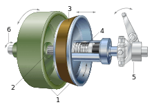
1. Cones: female cone (green), male cone (blue)
2. Shaft: male cone is sliding on splines
3. Friction material: usually on female cone, here on male cone
4. Spring: brings the male cone back after using the clutch control
5. Clutch control: separating both cones by pressing
6. Rotating direction: both direction of the axis are possible
The cone clutch transfers a higher torque than plate or disk clutches of the same size due to the wedging action and increased surface area. Cone clutches are generally now only used in low peripheral speed applications, although they were once common in automobiles and other combustion engine transmissions.[2]
They are usually now confined to very specialist transmissions used in racing, rallying, or in extreme off-road vehicles, although they are common in power boats.[3] This is because the clutch does not have to be pushed in all the way and the gears will be changed quicker. Small cone clutches are used in synchronizer mechanisms in manual transmissions and some limited-slip differentials.[4]
References
- Rao, T Krishna (2010). Design Of Machine Elements, Volume 2. I. K. International Pvt Ltd. p. 453. ISBN 9789380026633.
- Dick, Robert (2013). Auto Racing Comes of Age: A Transatlantic View of the Cars, Drivers and Speedways, 1900-1925. McFarland. pp. 22, 69, 80, 111, 164, 201. ISBN 9780786488117.
- "Diesel Power '88". Motor Boating & Sailing. 160 (1): 74. July 1987.
- Erjavec, Jack (2003). TechOne: Manual transmissions. Cengage Learning. p. 215. ISBN 9781401834005.
External links
| Wikimedia Commons has media related to Cone clutches. |