Computer-aided engineering
Computer-aided engineering (CAE) is the broad usage of computer software to aid in engineering analysis tasks. It includes finite element analysis (FEA), computational fluid dynamics (CFD), multibody dynamics (MBD), durability and optimization. It is included with computer-aided design (CAD) and computer-aided manufacturing (CAM) in the collective abbreviation "CAx".
Overview
Computer aided engineering primarily uses Computer Aided Design (CAD) software, which are sometimes called CAE tools. CAE tools are being used, for example, to analyse the robustness and performance of components and assemblies. The term encompasses simulation, validation, and optimisation of products and manufacturing tools. In the future, CAE systems will be major providers of information to help support design teams in decision making. Computer-aided engineering is used in many fields such as automotive, aviation, space, and shipbuilding industries.[1]
In regard to information networks, CAE systems are individually considered a single node on a total information network and each node may interact with other nodes on the network.
CAE systems can provide support to businesses. This is achieved by the use of reference architectures and their ability to place information views on the business process. Reference architecture is the basis from which information model, especially product and manufacturing models.
The term CAE has also been used by some in the past to describe the use of computer technology within engineering in a broader sense than just engineering analysis. It was in this context that the term was coined by Jason Lemon, founder of SDRC in the late 1970s. This definition is however better known today by the terms CAx and PLM.[2]
CAE fields and phases
CAE areas covered include:
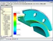
- Stress analysis on components and assemblies using Finite Element Analysis (FEA);
- Thermal and fluid flow analysis Computational fluid dynamics (CFD);
- Multibody dynamics (MBD) and Kinematics;
- Analysis tools for process simulation for operations such as casting, molding, and die press forming.
- Optimization of the product or process.
In general, there are three phases in any computer-aided engineering task:
- Pre-processing – defining the model and environmental factors to be applied to it. (typically a finite element model, but facet, voxel and thin sheet methods are also used)
- Analysis solver (usually performed on high powered computers)
- Post-processing of results (using visualization tools)
This cycle is iterated, often many times, either manually or with the use of commercial optimization software.
CAE in the automotive industry
CAE tools are very widely used in the automotive industry. In fact, their use has enabled the automakers to reduce product development cost and time while improving the safety, comfort, and durability of the vehicles they produce. The predictive capability of CAE tools has progressed to the point where much of the design verification is now done using computer simulations (diagnosis) rather than physical prototype testing. CAE dependability is based upon all proper assumptions as inputs and must identify critical inputs (BJ). Even though there have been many advances in CAE, and it is widely used in the engineering field, physical testing is still a must. It is used for verification and model updating, to accurately define loads and boundary conditions and for final prototype sign-off.
The future of CAE in the product development process
Even though CAE has built a strong reputation as a verification, troubleshooting and analysis tool, there is still a perception that sufficiently accurate results come rather late in the design cycle to really drive the design. This can be expected to become a problem as modern products become ever more complex. They include smart systems, which leads to an increased need for multi-physics analysis including controls, and contain new lightweight materials, to which engineers are often less familiar. CAE software companies and manufacturers are constantly looking for tools and process improvements to change this situation. On the software side, they are constantly looking to develop more powerful solvers, better use computer resources and include engineering knowledge in pre- and post-processing. On the process side, they try to achieve a better alignment between 3D CAE, 1D System Simulation and physical testing. This should increase modeling realism and calculation speed. On top of that, they try to better integrate CAE in the overall product lifecycle management. In this way, they can connect product design with product use, which is an absolute must for smart products. Such an enhanced engineering process is also referred to as predictive engineering analytics.[3][4]
See also
- Computer representation of surfaces
- Finite element analysis (FEA/FEM)
- Computational fluid dynamics (CFD)
- Computational electromagnetics (CEM)
- Multibody dynamics (MBD)
- Electronic design automation (EDA)
- Multidisciplinary design optimization (MDO)
- Comparison of CAD editors for CAE
- Virtual prototyping
- Finite element updating
- Predictive engineering analytics
References
- Saracoglu, B. O. (2006). "Identification of Technology Performance Criteria for CAD/CAM/CAE/CIM/CAL in Shipbuilding Industry". 2006 Technology Management for the Global Future - PICMET 2006 Conference. pp. 1635–1646. doi:10.1109/PICMET.2006.296739. ISBN 1-890843-14-8.CS1 maint: ref=harv (link)
- Marks, Peter. "2007: In Remembrance of Dr. Jason A. Lemon, CAE pioneer". gfxspeak.com. Retrieved 2 Jul 2011.
- Van der Auweraer, Herman; Anthonis, Jan; De Bruyne, Stijn; Leuridan, Jan (2012). "Virtual engineering at work: the challenges for designing mechatronic products". Engineering with Computers. 29 (3): 389–408. doi:10.1007/s00366-012-0286-6.
- Seong Wook Cho; Seung Wook Kim; Jin-Pyo Park; Sang Wook Yang; Young Choi (2011). "Engineering collaboration framework with CAE analysis data". International Journal of Precision Engineering and Manufacturing. 12.
Further reading
- B. Raphael and I.F.C. Smith (2003). Fundamentals of computer aided engineering. John Wiley. ISBN 978-0-471-48715-9.
External links
| Wikimedia Commons has media related to Computer-aided engineering. |
- Why do we need a CAE Software or Numerical Simulations?
- Computer Aided Engineering Journal WP:LINKROT (FEA, CAD, ...)
- Integrated Computer Aided Engineering Journal
- CAE AVI-gallery at CompMechLab site, Russia
- Computer-Aided Civil and Infrastructure Engineering
- Predictive engineering analytics
| Civil |  | |
|---|---|---|
| Mechanical | ||
| Electrical | ||
| Chemical | ||
| Interdisciplinary | ||
| Glossaries | ||
| ||
| Authority control |
|
|---|