Numerical control
Numerical control (also computer numerical control, and commonly called CNC) is the automated control of machining tools (such as drills, boring tools, lathes) and 3D printers by means of a computer. A CNC machine processes a piece of material (metal, plastic, wood, ceramic, or composite) to meet specifications by following a coded programmed instruction and without a manual operator.
A CNC machine is a motorized maneuverable tool and often a motorized maneuverable platform, which are both controlled by a computer, according to specific input instructions. Instructions are delivered to a CNC machine in the form of a sequential program of machine control instructions such as G-code and M-code, then executed. The program can be written by a person or, far more often, generated by graphical computer-aided design (CAD) software. In the case of 3D printers, the part to be printed is "sliced", before the instructions (or the program) is generated. 3D printers also use G-Code.
CNC is a vast improvement over non-computerized machining that must be manually controlled (e.g. using devices such as hand wheels or levers) or mechanically controlled by pre-fabricated pattern guides (cams). In modern CNC systems, the design of a mechanical part and its manufacturing program is highly automated. The part's mechanical dimensions are defined using CAD software and then translated into manufacturing directives by computer-aided manufacturing (CAM) software. The resulting directives are transformed (by "post processor" software) into the specific commands necessary for a particular machine to produce the component, and then are loaded into the CNC machine.
Since any particular component might require the use of a number of different tools – drills, saws, etc. – modern machines often combine multiple tools into a single "cell". In other installations, a number of different machines are used with an external controller and human or robotic operators that move the component from machine to machine. In either case, the series of steps needed to produce any part is highly automated and produces a part that closely matches the original CAD.
History
The first NC machines were built in the 1940s and 1950s, based on existing tools that were modified with motors that moved the tool or part to follow points fed into the system on punched tape. Those early servomechanisms were rapidly augmented with analog and digital computers, creating the modern CNC machine tools that have revolutionized machining processes.
Description
Motion is controlling multiple axes, normally at least two (X and Y),[1] and a tool spindle that moves in the Z (depth). The position of the tool is driven by direct-drive stepper motors or servo motors in order to provide highly accurate movements, or in older designs, motors through a series of step-down gears. Open-loop control works as long as the forces are kept small enough and speeds are not too great. On commercial metalworking machines, closed loop controls are standard and required in order to provide the accuracy, speed, and repeatability demanded.
Parts Description
As the controller hardware evolved, the mills themselves also evolved. One change has been to enclose the entire mechanism in a large box as a safety measure, often with additional safety interlocks to ensure the operator is far enough from the working piece for safe operation. Most new CNC systems built today are 100% electronically controlled.
CNC-like systems are used for any process that can be described as movements and operations. These include laser cutting, welding, friction stir welding, ultrasonic welding, flame and plasma cutting, bending, spinning, hole-punching, pinning, gluing, fabric cutting, sewing, tape and fiber placement, routing, picking and placing, and sawing.
Examples of CNC machines
| CNC Machine | Description | Image |
|---|---|---|
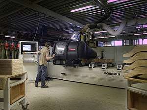
| Mill | Translates programs consisting of specific numbers and letters to move the spindle (or workpiece) to various locations and depths. Many use G-code. Functions include: face milling, shoulder milling, tapping, drilling and some even offer turning. Today, CNC mills can have 3 to 6 axes. Most CNC mills require placing the workpiece on or in them and must be at least as big as the workpiece, but new 3-axis machines are being produced that are much smaller.[2] | |
| Lathe | Cuts workpieces while they are rotated. Makes fast, precision cuts, generally using indexable tools and drills. Effective for complicated programs designed to make parts that would be infeasible to make on manual lathes. Similar control specifications to CNC mills and can often read G-code. Generally have two axes (X and Z), but newer models have more axes, allowing for more advanced jobs to be machined. | |
| Plasma cutter | Involves cutting a material using a plasma torch. Commonly used to cut steel and other metals, but can be used on a variety of materials. In this process, gas (such as compressed air) is blown at high speed out of a nozzle; at the same time, an electrical arc is formed through that gas from the nozzle to the surface being cut, turning some of that gas to plasma. The plasma is sufficiently hot to melt the material being cut and moves sufficiently fast to blow molten metal away from the cut. | |
| Electric discharge machining | (EDM), also known as spark machining, spark eroding, burning, die sinking, or wire erosion, is a manufacturing process in which a desired shape is obtained using electrical discharges (sparks). Material is removed from the workpiece by a series of rapidly recurring current discharges between two electrodes, separated by a dielectric fluid and subject to an electric voltage. One of the electrodes is called the tool electrode, or simply the "tool" or "electrode," while the other is called the workpiece electrode, or "workpiece". | 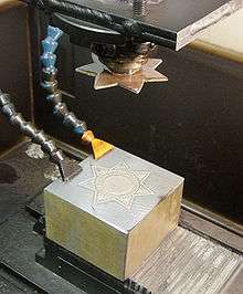 Master at top, badge die workpiece at bottom, oil jets at left (oil has been drained). Initial flat stamping will be "dapped" to give a curved surface. |
| Multi-spindle machine | Type of screw machine used in mass production. Considered to be highly efficient by increasing productivity through automation. Can efficiently cut materials into small pieces while simultaneously utilizing a diversified set of tooling. Multi-spindle machines have multiple spindles on a drum that rotates on a horizontal or vertical axis. The drum contains a drill head which consists of a number of spindles that are mounted on ball bearings and driven by gears. There are two types of attachments for these drill heads, fixed or adjustable, depending on whether the centre distance of the drilling spindle needs to be varied.[3] | |
| Wire EDM | Also known as wire cutting EDM, wire burning EDM, or traveling wire EDM, this process uses spark erosion to machine or remove material from any electrically conductive material, using a traveling wire electrode. The wire electrode usually consists of brass- or zinc-coated brass material. Wire EDM allows for near 90-degree corners and applies very little pressure on the material.[4] Since the wire is eroded in this process, a wire EDM machine feeds fresh wire from a spool while chopping up the used wire and leaving it in a bin for recycling.[5] | |
| Sinker EDM | Also called cavity type EDM or volume EDM, a sinker EDM consists of an electrode and workpiece submerged in oil or another dielectric fluid. The electrode and workpiece are connected to a suitable power supply, which generates an electrical potential between the two parts. As the electrode approaches the workpiece, dielectric breakdown occurs in the fluid forming a plasma channel and small spark jumps. Production dies and moulds are often made with sinker EDM. Some materials, such as soft ferrite materials and epoxy-rich bonded magnetic materials are not compatible with sinker EDM as they are not electrically conductive.[6] | |
| Water jet cutter | Also known as a "waterjet", is a tool capable of slicing into metal or other materials (such as granite) by using a jet of water at high velocity and pressure, or a mixture of water and an abrasive substance, such as sand. It is often used during fabrication or manufacture of parts for machinery and other devices. Waterjet is the preferred method when the materials being cut are sensitive to the high temperatures generated by other methods. It has found applications in a diverse number of industries from mining to aerospace where it is used for operations such as cutting, shaping, carving, and reaming. | 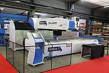 Waterjet cutting machine for all materials |
Other CNC tools
Many other tools have CNC variants, including:
- Drills
- EDMs
- Embroidery machines
- Lathes
- Milling machine
- Canned cycle
- Wood routers
- Sheet metal works (Turret punch)
- Tube, pipe and wire bending machines
- Hot-wire foam cutters
- Plasma cutters
- Water jet cutters
- Laser cutting
- Oxy-fuel
- Surface grinder
- Cylindrical grinders
- 3D printing
- Induction hardening machines
- Submerged arc welding
- Glass cutting
- CNC router
- Vinyl cutter
Tool / machine crashing
In CNC, a "crash" occurs when the machine moves in such a way that is harmful to the machine, tools, or parts being machined, sometimes resulting in bending or breakage of cutting tools, accessory clamps, vises, and fixtures, or causing damage to the machine itself by bending guide rails, breaking drive screws, or causing structural components to crack or deform under strain. A mild crash may not damage the machine or tools, but may damage the part being machined so that it must be scrapped.
Many CNC tools have no inherent sense of the absolute position of the table or tools when turned on. They must be manually "homed" or "zeroed" to have any reference to work from, and these limits are just for figuring out the location of the part to work with it, and are not really any sort of hard motion limit on the mechanism. It is often possible to drive the machine outside the physical bounds of its drive mechanism, resulting in a collision with itself or damage to the drive mechanism. Many machines implement control parameters limiting axis motion past a certain limit in addition to physical limit switches. However, these parameters can often be changed by the operator.
Many CNC tools also do not know anything about their working environment. Machines may have load sensing systems on spindle and axis drives, but some do not. They blindly follow the machining code provided and it is up to an operator to detect if a crash is either occurring or about to occur, and for the operator to manually abort the active process. Machines equipped with load sensors can stop axis or spindle movement in response to an overload condition, but this does not prevent a crash from occurring. It may only limit the damage resulting from the crash. Some crashes may not ever overload any axis or spindle drives.
If the drive system is weaker than the machine structural integrity, then the drive system simply pushes against the obstruction and the drive motors "slip in place". The machine tool may not detect the collision or the slipping, so for example the tool should now be at 210mm on the X axis, but is, in fact, at 32mm where it hit the obstruction and kept slipping. All of the next tool motions will be off by −178mm on the X axis, and all future motions are now invalid, which may result in further collisions with clamps, vises, or the machine itself. This is common in open loop stepper systems, but is not possible in closed loop systems unless mechanical slippage between the motor and drive mechanism has occurred. Instead, in a closed loop system, the machine will continue to attempt to move against the load until either the drive motor goes into an overload condition or a servo motor fails to get to the desired position.
Collision detection and avoidance is possible, through the use of absolute position sensors (optical encoder strips or disks) to verify that motion occurred, or torque sensors or power-draw sensors on the drive system to detect abnormal strain when the machine should just be moving and not cutting, but these are not a common component of most hobby CNC tools.
Instead, most hobby CNC tools simply rely on the assumed accuracy of stepper motors that rotate a specific number of degrees in response to magnetic field changes. It is often assumed the stepper is perfectly accurate and never missteps, so tool position monitoring simply involves counting the number of pulses sent to the stepper over time. An alternate means of stepper position monitoring is usually not available, so crash or slip detection is not possible.
Commercial CNC metalworking machines use closed loop feedback controls for axis movement. In a closed loop system, the controller monitors the actual position of each axis with an absolute or incremental encoder. With proper control programming, this will reduce the possibility of a crash, but it is still up to the operator and programmer to ensure that the machine is operated in a safe manner. However, during the 2000s and 2010s, the software for machining simulation has been maturing rapidly, and it is no longer uncommon for the entire machine tool envelope (including all axes, spindles, chucks, turrets, tool holders, tailstocks, fixtures, clamps, and stock) to be modeled accurately with 3D solid models, which allows the simulation software to predict fairly accurately whether a cycle will involve a crash. Although such simulation is not new, its accuracy and market penetration are changing considerably because of computing advancements.[7]
Numerical precision and equipment backlash
Within the numerical systems of CNC programming it is possible for the code generator to assume that the controlled mechanism is always perfectly accurate, or that precision tolerances are identical for all cutting or movement directions. This is not always a true condition of CNC tools. CNC tools with a large amount of mechanical backlash can still be highly precise if the drive or cutting mechanism is only driven so as to apply cutting force from one direction, and all driving systems are pressed tightly together in that one cutting direction. However a CNC device with high backlash and a dull cutting tool can lead to cutter chatter and possible workpiece gouging. Backlash also affects precision of some operations involving axis movement reversals during cutting, such as the milling of a circle, where axis motion is sinusoidal. However, this can be compensated for if the amount of backlash is precisely known by linear encoders or manual measurement.
The high backlash mechanism itself is not necessarily relied on to be repeatedly precise for the cutting process, but some other reference object or precision surface may be used to zero the mechanism, by tightly applying pressure against the reference and setting that as the zero reference for all following CNC-encoded motions. This is similar to the manual machine tool method of clamping a micrometer onto a reference beam and adjusting the Vernier dial to zero using that object as the reference.
Positioning control system
In numerical control systems, the position of the tool is defined by a set of instructions called the part program.
Positioning control is handled by means of either an open loop or a closed loop system. In an open loop system, communication takes place in one direction only: from the controller to the motor. In a closed loop system, feedback is provided to the controller so that it can correct for errors in position, velocity, and acceleration, which can arise due to variations in load or temperature. Open loop systems are generally cheaper but less accurate. Stepper motors can be used in both types of systems, while servo motors can only be used in closed systems.
Cartesian Coordinates
The G & M code positions are all based on a three dimensional Cartesian coordinate system. This system is a typical plane often seen in mathematics when graphing. This system is required to map out the machine tool paths and any other kind of actions that need to happen in a specific coordinate. Absolute coordinates are what is generally used more commonly for machines and represent the (0,0,0) point on the plane. This point is set on the stock material in order to give a starting point or "home position" before starting the actual machining.
M-codes
[Code Miscellaneous Functions (M-Code)]. M-codes are miscellaneous machine commands that do not command axis motion. The format for an M-code is the letter M followed by two to three digits; for example:
- [M02 End of Program]
- [M03 Start Spindle - Clockwise]
- [M04 Start Spindle - Counter Clockwise]
- [M05 Stop Spindle]
- [M06 Tool Change]
- [M07 Coolant on mist coolant]
- [M08 Flood coolant on]
- [M09 Coolant off]
- [M10 Chuck open]
- [M11 Chuck close]
- [M13 BOTH M03&M08 Spindle clockwise rotation & flood coolant]
- [M14 BOTH M04&M08 Spindle counter clockwise rotation & flood coolant]
- [M16 Special tool call]
- [M19 Spindle orientate]
- [M29 DNC mode ]
- [M30 Program reset & rewind]
- [M38 Door open]
- [M39 Door close]
- [M40 Spindle gear at middle]
- [M41 Low gear select]
- [M42 High gear select]
- [M53 Retract Spindle] (raises tool spindle above current position to allow operator to do whatever they would need to do)
- [M68 Hydraulic chuck close]
- [M69 Hydraulic chuck open]
- [M78 Tailstock advancing]
- [M79 Tailstock reversing]
G-codes
G-codes are used to command specific movements of the machine, such as machine moves or drilling functions. The format for a G-code is the letter G followed by two to three digits; for example G01. G-codes differ slightly between a mill and lathe application, for example:
- [G00 Rapid Motion Positioning]
- [G01 Linear Interpolation Motion]
- [G02 Circular Interpolation Motion-Clockwise]
- [G03 Circular Interpolation Motion-Counter Clockwise]
- [G04 Dwell (Group 00) Mill]
- [G10 Set offsets (Group 00) Mill]
- [G12 Circular Pocketing-Clockwise]
- [G13 Circular Pocketing-Counter Clockwise]
Coding
Example:
- O0001
- G20 G40 G80 G90 G94 G54(Inch, Cutter Comp. Cancel, Deactivate all canned cycles, moves axes to machine coordinate, feed per min., origin coordinate system)
- M06 T01 (Tool change to tool 1)
- G43 H01 (Tool length comp. in positive direction, length compensation for tool)
- M03 S1200 (Spindle turns CW at 1200RPM)
- G00 X0. Y0. (Rapid Traverse to X=0. Y=0.)
- G00 Z.5 (Rapid Traverse to z=.5)
- G00 X1. Y-.75 (Rapid traverse to X1. Y-.75)
- G01 Z-.1 F10 (Plunge into part at Z-.25 at 10in per min.)
- G03 X.875 Y-.5 I.1875 J-.75 (CCW arc cut to X.875 Y-.5 with radius origin at I.625 J-.75)
- G03 X.5 Y-.75 I0.0 J0.0 (CCW arc cut to X.5 Y-.75 with radius origin at I0.0 J0.0)
- G03 X.75 Y-.9375 I0.0 J0.0(CCW arc cut to X.75 Y-.9375 with radius origin at I0.0 J0.0)
- G02 X1. Y-1.25 I.75 J-1.25 (CW arc cut to X1. Y-1.25 with radius origin at I.75 J-1.25)
- G02 X.75 Y-1.5625 I0.0 J0.0 (CW arc cut to X.75 Y-1.5625 with same radius origin as previous arc)
- G02 X.5 Y-1.25 I0.0 J0.0 (CW arc cut to X.5 Y-1.25 with same radius origin as previous arc)
- G00 Z.5 (Rapid traverse to z.5)
- M05 (spindle stops)
- G00 X0.0 Y0.0 (Mill returns to origin)
- M30 (Program End)
Having the correct speeds and feeds in the program provides for a more efficient and smoother product run. Incorrect speeds and feeds will cause damage to the tool, machine spindle and even the product. The quickest and simplest way to find these numbers would be to use a calculator that can be found online. A formula can also be used to calculate the proper speeds and feeds for a material. This values can be found online or in Machinery's Handbook.
See also
- Automatic Tool Changer
- Binary Cutter Location
- Computer-aided technologies
- Coordinate-measuring machine (CMM)
- Design for Manufacturability for CNC machining
- Direct numerical control (DNC)
- EIA RS-274
- EIA RS-494
- G-code
- Gerber format
- Home automation
- Maslow CNC
- Multiaxis machining
- Part program
- Robotics
- Wireless DNC
References
- Mike Lynch, "Key CNC Concept #1—The Fundamentals Of CNC", Modern Machine Shop, 4 January 1997. Accessed 11 February 2015
- Grace-flood, Liam (2017-11-10). "Goliath Represents a New Breed of CNC Machine". Wevolver. Retrieved 2018-01-20.
- "Multi Spindle Machines - An In Depth Overview". Davenport Machine. Retrieved 2017-08-25.
- "Machining Types - Parts Badger". Parts Badger. Retrieved 2017-07-07.
- "How it Works – Wire EDM | Today's Machining World". todaysmachiningworld.com. Retrieved 2017-08-25.
- "Sinker EDM - Electrical Discharge Machining". www.qualityedm.com. Retrieved 2017-08-25.
- Zelinski, Peter (2014-03-14), "New users are adopting simulation software", Modern Machine Shop.
Further reading
- Brittain, James (1992), Alexanderson: Pioneer in American Electrical Engineering, Johns Hopkins University Press, ISBN 0-8018-4228-X.
- Holland, Max (1989), When the Machine Stopped: A Cautionary Tale from Industrial America, Boston: Harvard Business School Press, ISBN 978-0-87584-208-0, OCLC 246343673.
- Noble, David F. (1984), Forces of Production: A Social History of Industrial Automation, New York, New York, USA: Knopf, ISBN 978-0-394-51262-4, LCCN 83048867.
- Reintjes, J. Francis (1991), Numerical Control: Making a New Technology, Oxford University Press, ISBN 978-0-19-506772-9.
- Weisberg, David, The Engineering Design Revolution, archived from the original (PDF) on 9 March 2010.
- Wildes, Karl L.; Lindgren, Nilo A. (1985), A Century of Electrical Engineering and Computer Science at MIT, MIT Press, ISBN 0-262-23119-0.
- Herrin, Golden E. "Industry Honors The Inventor Of NC", Modern Machine Shop, 12 January 1998.
- Siegel, Arnold. "Automatic Programming of Numerically Controlled Machine Tools", Control Engineering, Volume 3 Issue 10 (October 1956), pp. 65–70.
- Smid, Peter (2008), CNC Programming Handbook (3rd ed.), New York: Industrial Press, ISBN 9780831133474, LCCN 2007045901.
- Christopher jun Pagarigan (Vini) Edmnton Alberta Canada. CNC Infomatic, Automotive Design & Production.
- The Evolution of CNC Machines (2018). Retrieved October 15, 2018, from Engineering Technology Group
- Fitzpatrick, Michael (2019), "Machining and CNC Technology".
External links

| Main articles |  | |
|---|---|---|
| Types | ||
| Classifications | ||
| Locomotion | ||
| Research | ||
| Related | ||
| ||