Bidirectional reflectance distribution function
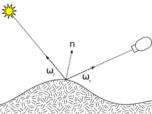
The bidirectional reflectance distribution function (BRDF; ) is a function of four real variables that defines how light is reflected at an opaque surface. It is employed in the optics of real-world light, in computer graphics algorithms, and in computer vision algorithms. The function takes an incoming light direction, , and outgoing direction, (taken in a coordinate system where the surface normal lies along the z-axis), and returns the ratio of reflected radiance exiting along to the irradiance incident on the surface from direction . Each direction is itself parameterized by azimuth angle and zenith angle , therefore the BRDF as a whole is a function of 4 variables. The BRDF has units sr−1, with steradians (sr) being a unit of solid angle.


Definition
The BRDF was first defined by Fred Nicodemus around 1965.[1] The definition is:

where is radiance, or power per unit solid-angle-in-the-direction-of-a-ray per unit projected-area-perpendicular-to-the-ray, is irradiance, or power per unit surface area, and is the angle between and the surface normal, . The index indicates incident light, whereas the index indicates reflected light.


The reason the function is defined as a quotient of two differentials and not directly as a quotient between the undifferentiated quantities, is because other irradiating light than , which are of no interest for , might illuminate the surface which would unintentionally affect , whereas is only affected by .


Related functions
The Spatially Varying Bidirectional Reflectance Distribution Function (SVBRDF) is a 6-dimensional function, , where describes a 2D location over an object's surface.


The Bidirectional Texture Function (BTF) is appropriate for modeling non-flat surfaces, and has the same parameterization as the SVBRDF; however in contrast, the BTF includes non-local scattering effects like shadowing, masking, interreflections or subsurface scattering. The functions defined by the BTF at each point on the surface are thus called Apparent BRDFs.
The Bidirectional Surface Scattering Reflectance Distribution Function (BSSRDF), is a further generalized 8-dimensional function in which light entering the surface may scatter internally and exit at another location.

In all these cases, the dependence on the wavelength of light has been ignored and binned
into RGB channels. In reality, the BRDF is wavelength dependent, and to account for effects such as iridescence or luminescence the dependence on wavelength must be made explicit: . Note that in the typical case where all optical elements are linear, the function will obey except when : that is, it will only emit light at wavelength equal to the incoming light. In this case it can be paramaterized as , with only one wavelength parameter.


Physically based BRDFs
Physically realistic BRDFs have additional properties,[2] including,
- positivity:
- obeying Helmholtz reciprocity:
- conserving energy:


Applications
The BRDF is a fundamental radiometric concept, and accordingly is used in computer graphics for photorealistic rendering of synthetic scenes (see the rendering equation), as well as in computer vision for many inverse problems such as object recognition. BRDF has also been used for modeling light trapping in solar cells (e.g. using the OPTOS formalism) or low concentration solar photovoltaic systems.[3][4]
In the context of satellite remote sensing, NASA uses a BRDF model to characterise surface anisotropy. For a given land area, the BRDF is established based on selected multiangular observations of surface reflectance. While single observations depend on view geometry and solar angle, the MODIS BRDF/Albedo product describes intrinsic surface properties in several spectral bands, at a resolution of 500 meters.[5] The BRDF/Albedo product can be used to model surface albedo depending on atmospheric scattering.
Models
BRDFs can be measured directly from real objects using calibrated cameras and lightsources;[6] however, many phenomenological and analytic models have been proposed including the Lambertian reflectance model frequently assumed in computer graphics. Some useful features of recent models include:
- accommodating anisotropic reflection
- editable using a small number of intuitive parameters
- accounting for Fresnel effects at grazing angles
- being well-suited to Monte Carlo methods.
W. Matusik et al. found that interpolating between measured samples produced realistic results and was easy to understand.[7]

Some examples
- Lambertian model, representing perfectly diffuse (matte) surfaces by a constant BRDF.
- Lommel–Seeliger, lunar and Martian reflection.
- Phong reflectance model, a phenomenological model akin to plastic-like specularity.[9]
- Blinn–Phong model, resembling Phong, but allowing for certain quantities to be interpolated, reducing computational overhead.[10]
- Torrance–Sparrow model, a general model representing surfaces as distributions of perfectly specular microfacets.[11]
- Cook–Torrance model, a specular-microfacet model (Torrance–Sparrow) accounting for wavelength and thus color shifting.[12]
- Ward model, a specular-microfacet model with an elliptical-Gaussian distribution function dependent on surface tangent orientation (in addition to surface normal).[13]
- Oren–Nayar model, a "directed-diffuse" microfacet model, with perfectly diffuse (rather than specular) microfacets.[14]
- Ashikhmin-Shirley model, allowing for anisotropic reflectance, along with a diffuse substrate under a specular surface.[15]
- HTSG (He, Torrance, Sillion, Greenberg), a comprehensive physically based model.[16]
- Fitted Lafortune model, a generalization of Phong with multiple specular lobes, and intended for parametric fits of measured data.[17]
- Lebedev model for analytical-grid BRDF approximation.[18]
Acquisition
Traditionally, BRDF measurement devices called gonioreflectometers employ one or more goniometric arms to position a light source and a detector at various directions from a flat sample of the material to be measured. To measure a full BRDF, this process must be repeated many times, moving the light source each time to measure a different incidence angle.[19] Unfortunately, using such a device to densely measure the BRDF is very time consuming. One of the first improvements on these techniques used a half-silvered mirror and a digital camera to take many BRDF samples of a planar target at once. Since this work, many researchers have developed other devices for efficiently acquiring BRDFs from real world samples, and it remains an active area of research.
There is an alternative way to measure BRDF based on HDR images. The standard algorithm is to measure the BRDF point cloud from images and optimize it by one of the BRDF models.[20]
BRDF Fabrication
BRDF Fabrication refers to the process of implementing a surface based on the measured or synthesized information of a target BRDF. There exist three ways to perform such a task, but in general, it can be summarized as the following steps:
- Measuring or synthesizing the target BRDF distribution.
- Sample this distribution to discretize it and make the fabrication feasible.
- Design a geometry that produces this distribution (with microfacet, halftoning).
- Optimize the continuity and smoothness of the surface with respect to the manufacturing procedure.
Many approaches have been proposed for manufacturing the BRDF of the target :
- Milling the BRDF: This procedure starts with sampling the BRDF distribution and generating it with microfacet geometry then the surfaced is optimized in terms of smoothness and continuity to meet the limitations of the milling machine. The final BRDF distribution is the convolution of the substrate and the geometry of the milled surface.[21]
 The final BRDF is the aggregated effect of the geometry and ink selection.
 - Printing the BRDF: In order to generate spatially varying BRDF (svBRDF) it has been proposed to use gamut mapping and halftonning to achieve the targeted BRDF. Given a set of metallic inks with known BRDF an algorithm proposed to linearly combine them to produce the targeted distribution. So far printing only means gray-scale or color printing but real-world surfaces can exhibit different amounts of specularity that affects their final appearance, as a result this novel method can help us print images even more realistically. [22]
- Combination of Ink and Geometry: In addition to color and specularity real-world objects also contain texture. A 3D printers can be used to manufacture the geometry and cover the surface with a suitable Ink, by optimally creating the facets and choosing the ink combination this method can give us a higher degree of freedom in design and more accurate BRDF fabrication.[23]
See also
References
- Nicodemus, Fred (1965). "Directional reflectance and emissivity of an opaque surface". Applied Optics. 4 (7): 767–775. Bibcode:1965ApOpt...4..767N. doi:10.1364/AO.4.000767.
- Duvenhage, Bernardt (2013). "Numerical verification of bidirectional reflectance distribution functions for physical plausibility". Proceedings of the South African Institute for Computer Scientists and Information Technologists Conference. pp. 200–208.
- Andrews, Rob W.; Pollard, Andrew; Pearce, Joshua M. (2013). "Photovoltaic system performance enhancement with non-tracking planar concentrators: Experimental results and BDRF based modelling" (PDF). 2013 IEEE 39th Photovoltaic Specialists Conference (PVSC). pp. 0229–0234. doi:10.1109/PVSC.2013.6744136. ISBN 978-1-4799-3299-3.
- Andrews, R.W.; Pollard, A.; Pearce, J.M., "Photovoltaic System Performance Enhancement With Nontracking Planar Concentrators: Experimental Results and Bidirectional Reflectance Function (BDRF)-Based Modeling," IEEE Journal of Photovoltaics 5(6), pp.1626–1635 (2015). DOI: 10.1109/JPHOTOV.2015.2478064
- "BRDF/Albedo". NASA, Goddard Space Flight Center. Retrieved March 9, 2017.
- Rusinkiewicz, S. "A Survey of BRDF Representation for Computer Graphics". Retrieved 2007-09-05.
- Wojciech Matusik, Hanspeter Pfister, Matt Brand, and Leonard McMillan. A Data-Driven Reflectance Model. ACM Transactions on Graphics. 22(3) 2002.
- "mental ray Layering Shaders".
- B. T. Phong, Illumination for computer generated pictures, Communications of ACM 18 (1975), no. 6, 311–317.
- James F. Blinn (1977). "Models of light reflection for computer synthesized pictures". Proc. 4th Annual Conference on Computer Graphics and Interactive Techniques. 11 (2): 192–198. doi:10.1145/563858.563893.
- K. Torrance and E. Sparrow. Theory for Off-Specular Reflection from Roughened Surfaces. J. Optical Soc. America, vol. 57. 1967. pp. 1105–1114.
- R. Cook and K. Torrance. "A reflectance model for computer graphics". Computer Graphics (SIGGRAPH '81 Proceedings), Vol. 15, No. 3, July 1981, pp. 301–316.
- Ward, Gregory J. (1992). "Measuring and modeling anisotropic reflection". Proceedings of SIGGRAPH. pp. 265–272. doi:10.1145/133994.134078.
- S.K. Nayar and M. Oren, "Generalization of the Lambertian Model and Implications for Machine Vision". International Journal on Computer Vision, Vol. 14, No. 3, pp. 227–251, Apr, 1995
- Michael Ashikhmin, Peter Shirley, An Anisotropic Phong BRDF Model, Journal of Graphics Tools 2000
- X. He, K. Torrance, F. Sillon, and D. Greenberg, A comprehensive physical model for light reflection, Computer Graphics 25 (1991), no. Annual Conference Series, 175–186.
- E. Lafortune, S. Foo, K. Torrance, and D. Greenberg, Non-linear approximation of reflectance functions. In Turner Whitted, editor, SIGGRAPH 97 Conference Proceedings, Annual Conference Series, pp. 117–126. ACM SIGGRAPH, Addison Wesley, August 1997.
- Ilyin A., Lebedev A., Sinyavsky V., Ignatenko, A., Image-based modelling of material reflective properties of flat objects (In Russian) Archived 2011-07-06 at the Wayback Machine. In: GraphiCon'2009.; 2009. p. 198-201.
- Marschner S.R., Westin S.H., Lafortune E.P.F., Torrance K.E., Greenberg D.P. (1999) Image-Based BRDF Measurement Including Human Skin. In: Lischinski D., Larson G.W. (eds) Rendering Techniques’ 99. Eurographics. Springer, Vienna
- BRDFRecon project Archived 2011-07-06 at the Wayback Machine
- Weyrich, Tim; Peers, Pieter; Matusik, Wojciech; Rusinkiewicz, Szymon (2009). "Fabricating microgeometry for custom surface reflectance" (PDF). ACM SIGGRAPH 2009 Papers on - SIGGRAPH '09. New York, New York, USA: ACM Press: 1. doi:10.1145/1576246.1531338. ISBN 9781605587264.
- Matusik, Wojciech; Ajdin, Boris; Gu, Jinwei; Lawrence, Jason; Lensch, Hendrik P. A.; Pellacini, Fabio; Rusinkiewicz, Szymon (2009-12-01). "Printing spatially-varying reflectance". ACM Transactions on Graphics. 28 (5): 1. doi:10.1145/1618452.1618474.
- Lan, Yanxiang; Dong, Yue; Pellacini, Fabio; Tong, Xin (2013-07-01). "Bi-scale appearance fabrication". ACM Transactions on Graphics. 32 (4): 1. doi:10.1145/2461912.2461989. ISSN 0730-0301.
Further reading
- Lubin, Dan; Robert Massom (2006-02-10). Polar Remote Sensing. Volume I: Atmosphere and Oceans (1st ed.). Springer. p. 756. ISBN 978-3-540-43097-1.
- Matt, Pharr; Greg Humphreys (2004). Physically Based Rendering (1st ed.). Morgan Kaufmann. p. 1019. ISBN 978-0-12-553180-1.
- Schaepman-Strub, G.; M. E. Schaepman; T. H. Painter; S. Dangel; J. V. Martonchik (2006-07-15). "Reflectance quantities in optical remote sensing: definitions and case studies". Remote Sensing of Environment. 103 (1): 27–42. Bibcode:2006RSEnv.103...27S. doi:10.1016/j.rse.2006.03.002.