Arrayed waveguide grating
Arrayed waveguide gratings (AWG) are commonly used as optical (de)multiplexers in wavelength division multiplexed (WDM) systems. These devices are capable of multiplexing many wavelengths into a single optical fiber, thereby increasing the transmission capacity of optical networks considerably.
The devices are based on a fundamental principle of optics that light waves of different wavelengths do not interfere linearly with each other. This means that, if each channel in an optical communication network makes use of light of a slightly different wavelength, then the light from many of these channels can be carried by a single optical fiber with negligible crosstalk between the channels. The AWGs are used to multiplex channels of several wavelengths onto a single optical fiber at the transmission end and are also used as demultiplexers to retrieve individual channels of different wavelengths at the receiving end of an optical communication network.
Operation of AWG devices
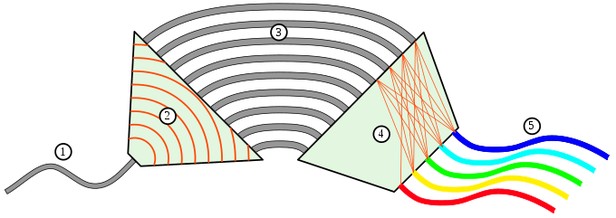
Conventional silica-based AWGs schematically shown in the above figure, are planar lightwave circuits fabricated by depositing doped and undoped layers of silica on a silicon substrate. The AWGs consist of a number of input (1) / output (5) couplers, a free space propagation region (2) and (4) and the grating waveguides (3). The grating consists of many waveguides with a constant length increment (ΔL). Light is coupled into the device via an optical fiber (1) connected to the input port. Light diffracting out of the input waveguide at the coupler/slab interface propagates through the free-space region (2) and illuminates the grating with a Gaussian distribution. Each wavelength of light coupled to the grating waveguides (3) undergoes a constant change of phase attributed to the constant length increment in grating waveguides. Light diffracted from each waveguide of the grating interferes constructively and gets refocused at the output waveguides (5), with the spatial position, the output channels, being wavelength dependent on the array phase shift.