Amtrak's 60 Hz traction power system
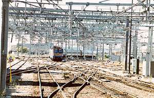
Amtrak operates a 60 Hz traction power system along the Northeast Corridor between New Haven, Connecticut[1] and Boston, Massachusetts. This system was built in the late 1990s and supplies locomotives with power from an overhead catenary system at 25 kV, 60 Hz. The system is also commonly known as the Northend Electrification, in contrast to the Southend Electrification that runs from New York City to Washington DC.
History
In 1992, Congress passed the Amtrak Authorization and Development Act requiring Amtrak to establish high-speed rail passenger service between New York City and Boston. The goal was to reduce travel time in this corridor from 4.5 hours to less than 3 hours. Revenue from this service was expected to play a critical role in helping Amtrak achieve operating self-sufficiency by 2003. Before Amtrak could begin high-speed rail service, 155 miles (249 km) of rail line between New Haven and Boston had to be electrified. Previously, electrified Metroliner service was available between Washington, D.C. and New Haven, Connecticut. At New Haven, Amtrak had to switch to a diesel locomotive to complete the trip to Boston. In addition to the higher operating speeds possible with electrified service, Amtrak also saves the time it spent on switching locomotives. By the time the project was complete, Amtrak was expected to have spent over $600 million to electrify the line between New Haven and Boston.[2] Including extensive track and infrastructure improvements besides the electrification, the project cost $1.6 billion.[3]
In December 1995, Amtrak awarded a $321 million contract to Balfour Beatty Construction, Inc./Mass. Electric Construction (BBC/MEC) to verify and complete the Morrison-Knudsen design and build the electrification system. The system was to be completed by June 1999; electrification system ground-breaking ceremony took place the following July.
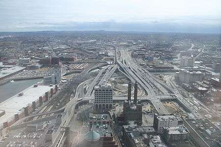
Amtrak's contractor faced a difficult working environment in the Boston Terminal Area because of the extensive work being undertaken for the Central Artery project, which involved over 500 employees in the South Boston Terminal area alone and entailed on-site storage of a large amount of heavy construction equipment and supplies. The Central Artery project was ongoing before the electrification project started. Another factor complicating electrification work in the Boston Terminal Area is the large volume of rail traffic. Over 250 Massachusetts Bay Transportation Authority (MBTA) commuter trains and 20 Amtrak trains operate through the area daily. As a result, taking track out of service to work on the electrification was sometimes difficult.
Electrification work on the five movable bridges between Old Saybrook and Mystic in Connecticut was also a challenge, as each one required a unique electrification design and construction solution. The bridges span busy waterways shared by pleasure craft, commercial carriers, and military traffic. Unlike most movable highway bridges, these bridges are usually open, and are closed only to accommodate approaching train traffic.[2]
After several delays, service with electric locomotives between New Haven and Boston began on January 31, 2000.[4] Amtrak began operating its higher-speed Acela Express service on December 11, 2000.[5]
Types of stations
System architecture

The basic system unit is an elementary electrical section consisting of a segment of one or more parallel tracks, each with a contiguous contact (or catenary or trolley) wire for the locomotive pantograph and an electrically separate feed wire. Elementary electrical sections are separated by section breaks where the contact and feeder wires can be interrupted with motor-operated air switches to isolate a section in the event of a fault or to permit maintenance.
An electrical section is a collection of elementary electrical sections, section breaks, air switches and paralleling stations between a substation and a switching station.
At each substation, utility-supplied single phase power is transformed and injected into the two electrical sections terminating at that substation. There are eight electrical sections in the system, two for each substation. The substations drive the contact and feed wires in a split phase arrangement so that each wire is at 25 kV with respect to the grounded running rails with 50 kV between them.
At periodically spaced paralleling stations within each electrical section the tracks' catenary wires are connected together to one side of an autotransformer and the feeder wires are connected together to the other side of the autotransformer. The autotransformer center tap is connected to the grounded running rails that return the current from the locomotives. The paralleling stations thus reduce voltage drops by feeding a locomotive from both directions along its contact wire and spreading the load across all the contact and feed wires of a multitrack system. The split-phase arrangement also gains the increased efficiency of operating at 50 kV while the highest voltage with respect to ground remains only 25 kV. (The same split-phase method is used in North American homes to supply high power loads such as air conditioners with the efficiency of a 240 V supply while retaining the safety advantages of a 120 V supply.)
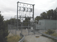
Substations
There are four substations between New Haven and Boston:
- Branford, CT
- New London, CT
- Warwick, RI
- Sharon, MA
Each station contains two 115 kV (single phase) to 50 kV (single phase with center tap) transformers to convert the utility supplied transmission voltage to 50 kV traction voltage. Output circuit breakers, and a capacitor based filter network are installed. The filter banks suppress the high frequency (that is anything above 60 Hz) harmonics on the catenary lines generated by locomotives' solid-state traction motor inverters. The filters also provide reactive power support and correct for power factor. Amtrak's 60 Hz electrification distributes power using ±25 kV from ground via a center tap of the 115/50 kV transformers. This system is also known as 2 × 25 kV.
Switching stations
Three switching stations are the equivalent of distribution level substations, which transform higher voltage electricity to the 25 kV voltage, and are located along the line which separate the different electrical sections (power zones):
- Westbrook, CT
- Richmond, RI
- Norton, MA
The switching stations contain three autotransformers similar to the paralleling stations (which have one), and also have additional circuit breakers to allow segmentation of catenary and cross-connection between power zones.
Electrical sections encompass both tracks between a substation and the adjacent switching stations. Normally no power flows from one side of a switching station to the other side; it is like two adjacent paralleling stations which serve different electrical sections. In the event that a substation is taken out of service, switching stations have additional circuit breakers which allow feeding an electrical section from the adjacent section.
Since switching stations, like substations, normally separate electrical sections with different supply sources (and thus different phase or voltage), a neutral section[6] always occupies the track between the two electrical sections.
In the event of a fault in one elementary electrical section, the switching station can 'back-feed' the far portion of the affected track from the non-affected track, which the supplying substation feeds the near end.
Paralleling stations
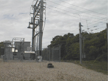
Eighteen paralleling stations are located at approximately six mile intervals[7] along the line. Each contains a single autotransformer (with the exception of Roxbury, which has two), automatic circuit breakers, motor-operated air switches, and a control shed. The autotransformers are rated at 10 MVA, 1.2% impedance, two winding, 27.5 kV.[8]
Each paralleling station bus is connected to both north and south track catenary and feeder lines via automatic circuit breakers. The autotransformer is connected to the bus bars by an additional circuit breaker. The track breakers at the paralleling stations trip on sensing no-voltage. Thus when a line fault causes the supplying substation breakers to trip, the paralleling stations also trip. This action separates the two tracks from one another electrically and allows the substation to automatically restore one of the tracks (the non-faulted one). After a variable time delay (to reduce simultaneous inrush current), over-voltage relays will re-shut the track circuit breakers on the non-faulted track.
List of stations

| MP[9] | State | Municipality | Type | Coordinates | Comments |
|---|---|---|---|---|---|
| 228.49 | MA | Boston (South) | N/A | End of electrification | |
| 226.12 | MA | Roxbury | paralleling station | 42.3331°N 71.0937°W | |
| 219.08 | MA | Readville | paralleling station | 42.2365°N 71.1343°W | |
| 212.36 | MA | Sharon | substation | 42.1442°N 71.1642°W | |
| 204.98 | MA | East Foxboro | paralleling station | 42.0456°N 71.2107°W | |
| 198.68 | MA | Norton | switching station | 41.969°N 71.2652°W | |
| 193.41 | MA | Attleboro | paralleling station | 41.903555°N 71.322914°W | |
| 187.60 | RI | Providence | paralleling station | 41.860604°N 71.406251°W | |
| 181.89 | RI | Elmwood | paralleling station | 41.798065°N 71.42868°W | |
| 176.94 | RI | Warwick | substation | 41.732459°N 71.440597°W | |
| 169.82 | RI | East Greenwich | paralleling station | 41.634505°N 71.463999°W | |
| 161.81 | RI | Exeter | paralleling station | 41.525942°N 71.518782°W | |
| 157.15 | RI | Kingston | paralleling station | 41.475541°N 71.57462°W | |
| 150.15 | RI | Richmond | switching station | 41.437637°N 71.689892°W | |
| 145.19 | RI | Bradford | paralleling station | 41.394712°N 71.760969°W | |
| 139.97 | CT | State Line | paralleling station | 41.3644°N 71.8403°W | |
| 134.70 | CT | Stonington | paralleling station | 41.3403°N 71.9254°W | |
| 129.50 | CT | Noank | paralleling station | 41.3234°N 71.9984°W | |
| 123.56 | CT | New London | substation | 41.3629°N 72.093°W | Transformers are grade separated from roadbed; catenary feeders run underground. |
| 117.54 | CT | Millstone | paralleling station | 41.3164°N 72.1644°W | |
| 109.30 | CT | Old Lyme | paralleling station | 41.2966°N 72.3044°W | |
| 103.10 | CT | Westbrook | switching station | 41.2900°N 72.4112°W | |
| 98.87 | CT | Grove Beach | paralleling station | 41.2768°N 72.4875°W | |
| 92.19 | CT | Madison | paralleling station | 41.2840°N 72.6112°W | |
| 86.10 | CT | Leetes Island | paralleling station | 41.2655°N 72.7250°W | |
| 78.96 | CT | Branford | substation | 41.2841°N 72.8537°W | Transformers located N. of I-95. |
| 73.6 | CT | Mill River Interlocking | N/A | 41.311281°N 72.911775°W | End of 25 kV, 60 Hz system |
See also
- 25 kV AC railway electrification
- Amtrak's 25 Hz Traction Power System operates along the southern portions of the Northeast Corridor
- SEPTA's 25 Hz Traction Power System
- List of railway electrification systems
- Overhead lines
- North–South Rail Link
References
Notes
- Specifically, Amtrak's 25 kV system begins at the Mill River Interlocking about two miles north of New Haven Station 41.311281°N 72.911775°W
- Report on Amtrak’s High-Speed Rail Electrification Project Federal Railroad Administration Inspector General Report No: RT-2000-020, December 14, 1999, accessed September 28, 2017
- https://www.nytimes.com/1999/03/10/nyregion/amtrak-unveils-its-bullet-to-boston.html
- Middleton, William D. (March 2003). "Super Railroad". Trains. 63 (3): 36–59. ISSN 0041-0934.
- Amtrak’s new Hit-Speed Service is Derailed by Mechanical Problem, LA Times/AP, December 13, 2000
- The terms 'phase break', 'neutral section', and 'dead section' are colloquially interchanged. Agarwal refers to these as 'neutral sections'. In the ex-PRR portions of Amtrak's system, they would be known as 'dead sections'.
- EMF, p. 5
- Natarajan, 453.
- Natarajan, p. 451
Further reading
- Environmental Impact Statement: Volume 1, Volume 2, Volume 3
- Agarwal, K.K. (2002). Automatic fault location and isolation system for the electric traction overhead lines. 2002 ASME/IEEE Joint Railroad Conference. p. 117. doi:10.1109/RRCON.2002.1000103..
- Audit Report of Amtrak's High Speed Rail Electrification Project, US Department of Transportation: Federal Railroad Administration, December 1999. Retrieved 12/26/2010.
- Chance, E.E. "System Compatibility of the HST", Railroad Conference, 1997., Proceedings of the 1997 IEEE/ASME Joint, pp 1–9, 1997. doi:10.1109/RRCON.1997.581346.
- EMF Monitoring on Amtrak's Northeast Corridor: Post-Electrification Measurements and Analysis, US Department of Transportation: Federal Railroad Administration, October 2006. Retrieved 12/26/2010.
- Natarajan, R.; Imece, A.F.; Popoff, J.; Agarwal, K.; Meliopoulos, S. "Approach to the analysis of Amtrak's systemwide grounding of the Northend Electrification Project", Power Engineering Society Summer Meeting, 1999, Vol 1, pp. 451–456. doi:10.1109/PESS.1999.784390.
- Sutherland, et al. Analysis of Harmonics, Flicker and Unbalance of Time-Varying Single-Phase Traction Loads on a Three-Phase System, Paper No. IPST05 - 091. Retrieved 12/26/2010.