4+1 architectural view model
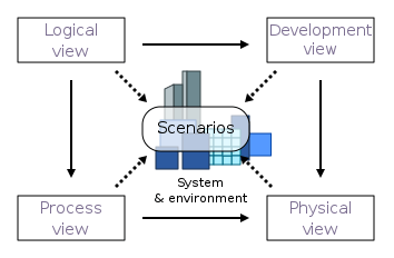
4+1 is a view model used for "describing the architecture of software-intensive systems, based on the use of multiple, concurrent views".[1] The views are used to describe the system from the viewpoint of different stakeholders, such as end-users, developers, system engineer, and project managers. The four views of the model are logical, development, process and physical view. In addition, selected use cases or scenarios are used to illustrate the architecture serving as the 'plus one' view. Hence, the model contains 4+1 views:[1]
- Logical view: The logical view is concerned with the functionality that the system provides to end-users. UML diagrams are used to represent the logical view, and include class diagrams, and state diagrams.[2]
- Process view: The process view deals with the dynamic aspects of the system, explains the system processes and how they communicate, and focuses on the run time behavior of the system. The process view addresses concurrency, distribution, integrator, performance, and scalability, etc. UML diagrams to represent process view include the sequence diagram, communication diagram, activity diagram.[3][2]
- Development view: The development view illustrates a system from a programmer's perspective and is concerned with software management. This view is also known as the implementation view. It uses the UML Component diagram to describe system components. UML Diagrams used to represent the development view include the Package diagram.[2]
- Physical view: The physical view depicts the system from a system engineer's point of view. It is concerned with the topology of software components on the physical layer as well as the physical connections between these components. This view is also known as the deployment view. UML diagrams used to represent the physical view include the deployment diagram.[2]
- Scenarios: The description of an architecture is illustrated using a small set of use cases, or scenarios, which become a fifth view. The scenarios describe sequences of interactions between objects and between processes. They are used to identify architectural elements and to illustrate and validate the architecture design. They also serve as a starting point for tests of an architecture prototype. This view is also known as the use case view.
The 4+1 view model is generic and is not restricted to any notation, tool or design method. Quoting Kruchten,
The “4+1” view model is rather “generic”: other notations and tools can be used, other design methods can be used, especially for the logical and process decompositions, but we have indicated the ones we have used with success.
— Philippe Kruchten, Architectural Blueprints—The “4+1” View Model of Software Architecture[1]
See also
References
- Kruchten, Philippe (1995, November). Architectural Blueprints — The “4+1” View Model of Software Architecture. IEEE Software 12 (6), pp. 42-50.
- Mikko Kontio (2008, July) Architectural manifesto: Designing software architectures, Part 5
- Hui, LM; Leung, CW; Fan, CK; Wong, TN (2004). "Modelling agent-based systems with UML". Proceedings of the Fifth Asia Pacific Industrial Engineering and Management Systems Conference.