Systems development life cycle
The systems development life cycle (SDLC), also referred to as the application development life-cycle, is a term used in systems engineering, information systems and software engineering to describe a process for planning, creating, testing, and deploying an information system.[1] The systems development lifecycle concept applies to a range of hardware and software configurations, as a system can be composed of hardware only, software only, or a combination of both.[2]
Overview
A systems development life cycle is composed of a number of clearly defined and distinct work phases which are used by systems engineers and systems developers to plan for, design, build, test, and deliver information systems. Like anything that is manufactured on an assembly line, an SDLC aims to produce high-quality systems that meet or exceed customer expectations, based on customer requirements, by delivering systems which move through each clearly defined phase, within scheduled time frames and cost estimates.[3] Computer systems are complex and often (especially with the recent rise of service-oriented architecture) link multiple traditional systems potentially supplied by different software vendors. To manage this level of complexity, a number of SDLC models or methodologies have been created, such as waterfall, spiral, Agile software development, rapid prototyping, incremental, and synchronize and stabilize.[4]
SDLC can be described along a spectrum of agile to iterative to sequential methodologies. Agile methodologies, such as XP and Scrum, focus on lightweight processes which allow for rapid changes (without necessarily following the pattern of SDLC approach) along the development cycle. Iterative methodologies, such as Rational Unified Process and dynamic systems development method, focus on limited project scope and expanding or improving products by multiple iterations. Sequential or big-design-up-front (BDUF) models, such as waterfall, focus on complete and correct planning to guide large projects and risks to successful and predictable results. Other models, such as anamorphic development, tend to focus on a form of development that is guided by project scope and adaptive iterations of feature development.
In project management a project can be defined both with a project life cycle (PLC) and an SDLC, during which slightly different activities occur. According to Taylor (2004), "the project life cycle encompasses all the activities of the project, while the systems development life cycle focuses on realizing the product requirements".[5]
SDLC is used during the development of an IT project, it describes the different stages involved in the project from the drawing board, through the completion of the project.
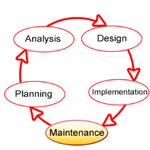
The SDLC is not a methodology per se, but rather a description of the phases in the life cycle of a software application. These phases (broadly speaking) are, investigation, analysis, design, build, test, implement, and maintenance and support. All software development methodologies (such as the more commonly known waterfall and scrum methodologies) follow the SDLC phases but the method of doing that varies vastly between methodologies. In the Scrum methodology, for example, one could say a single user story goes through all the phases of the SDLC within a single two-week sprint. Contrast this to the waterfall methodology, as another example, where every business requirement (recorded in the analysis phase of the SDLC in a document called the Business Requirements Specification) is translated into feature/functional descriptions (recorded in the design phase in a document called the Functional Specification) which are then all built in one go as a collection of solution features typically over a period of three to nine months, or more. These methodologies are obviously quite different approaches yet, they both contain the SDLC phases in which a requirement is born, then travels through the life cycle phases ending in the final phase of maintenance and support, after-which (typically) the whole life cycle starts again for a subsequent version of the software application.
History and details
The product life cycle describes the process for building information systems in a very deliberate, structured and methodical way, reiterating each stage of the product's life. The systems development life cycle, according to Elliott & Strachan & Radford (2004), "originated in the 1960s, to develop large scale functional business systems in an age of large scale business conglomerates. Information systems activities revolved around heavy data processing and number crunching routines".[6]
Several systems development frameworks have been partly based on SDLC, such as the structured systems analysis and design method (SSADM) produced for the UK government Office of Government Commerce in the 1980s. Ever since, according to Elliott (2004), "the traditional life cycle approaches to systems development have been increasingly replaced with alternative approaches and frameworks, which attempted to overcome some of the inherent deficiencies of the traditional SDLC".[6]
Phases
The system development life cycle framework provides a sequence of activities for system designers and developers to follow. It consists of a set of steps or phases in which each phase of the SDLC uses the results of the previous one.[7][8]
The SDLC adheres to important phases that are essential for developers—such as planning, analysis, design, and implementation—and are explained in the section below. This includes evaluation of the currently used system, information gathering, feasibility studies, and request approval. A number of SDLC models have been created, including waterfall, fountain, spiral, build and fix, rapid prototyping, incremental, synchronize, and stabilize.[9][10] The oldest of these, and the best known, is the waterfall model, a sequence of stages in which the output of each stage becomes the input for the next.[8] These stages can be characterized and divided up in different ways, including the following:[7][8][11][12]
- Preliminary analysis: Begin with a preliminary analysis, propose alternative solutions, describe costs and benefits, and submit a preliminary plan with recommendations.
- Conduct the preliminary analysis: Discover the organization's objectives and the nature and scope of the problem under study. Even if a problem refers only to a small segment of the organization itself, find out what the objectives of the organization itself are. Then see how the problem being studied fits in with them.
- Propose alternative solutions: After digging into the organization's objectives and specific problems, several solutions may have been discovered. However, alternate proposals may still come from interviewing employees, clients, suppliers, and/or consultants. Insight may also be gained by researching what competitors are doing.
- Cost benefit analysis: Analyze and describe the costs and benefits of implementing the proposed changes. In the end, the ultimate decision on whether to leave the system as is, improve it, or develop a new system will be guided by this and the rest of the preliminary analysis data.
- Systems analysis, requirements definition: Define project goals into defined functions and operations of the intended application. This involves the process of gathering and interpreting facts, diagnosing problems, and recommending improvements to the system. Project goals will be further aided by analysis of end-user information needs and the removal of any inconsistencies and incompleteness in these requirements.
- A series of steps followed by the developer include:[13]
- Collection of facts: Obtain end user requirements through documentation, client interviews, observation, and questionnaires.
- Scrutiny of the existing system: Identify pros and cons of the current system in-place, so as to carry forward the pros and avoid the cons in the new system.
- Analysis of the proposed system: Find solutions to the shortcomings described in step two and prepare the specifications using any specific user proposals.
- Systems design: At this step desired features and operations are described in detail, including screen layouts, business rules, process diagrams, pseudocode, and other documentation.
- Development: The real code is written here.
- Integration and testing: All the pieces are brought together into a special testing environment, then checked for errors, bugs, and interoperability.
- Acceptance, installation, deployment: This is the final stage of initial development, where the software is put into production and runs actual business.
- Maintenance: During the maintenance stage of the SDLC, the system is assessed/evaluated to ensure it does not become obsolete. This is also where changes are made to initial software.
- Evaluation: Some companies do not view this as an official stage of the SDLC, while others consider it to be an extension of the maintenance stage, and may be referred to in some circles as post-implementation review. This is where the system that was developed, as well as the entire process, is evaluated. Some of the questions that need to be answered include if the newly implemented system meets the initial business requirements and objectives, if the system is reliable and fault-tolerant, and if it functions according to the approved functional requirements. In addition to evaluating the software that was released, it is important to assess the effectiveness of the development process. If there are any aspects of the entire process (or certain stages) that management is not satisfied with, this is the time to improve.
- Disposal: In this phase, plans are developed for discontinuing the use of system information, hardware, and software and making the transition to a new system. The purpose here is to properly move, archive, discard, or destroy information, hardware, and software that is being replaced, in a manner that prevents any possibility of unauthorized disclosure of sensitive data. The disposal activities ensure proper migration to a new system. Particular emphasis is given to proper preservation and archiving of data processed by the previous system. All of this should be done in accordance with the organization's security requirements.[14]
In the following diagram, these stages of the systems development life cycle are divided in ten steps, from definition to creation and modification of IT work products:
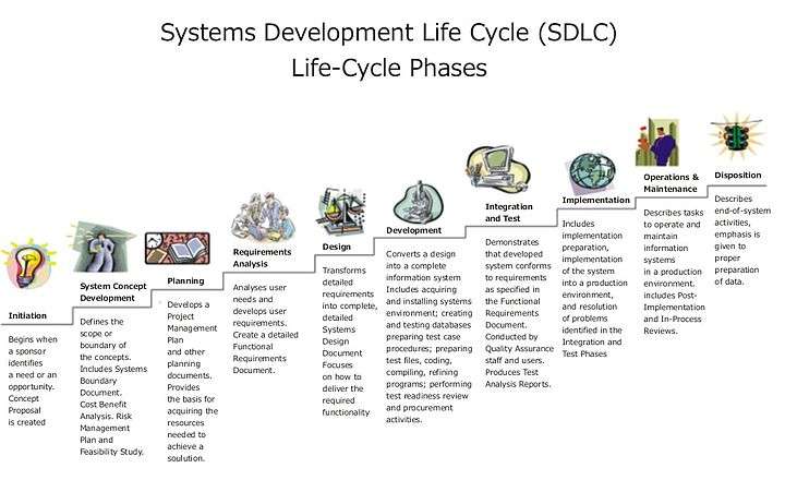
Not every project will require that the phases be sequentially executed. However, the phases are interdependent. Depending upon the size and complexity of the project, phases may be combined or may overlap.[7]
System investigation
First the IT system proposal is investigated. During this step, consider all current priorities that would be affected and how they should be handled. Before any system planning is done, a feasibility study should be conducted to determine if creating a new or improved system is a viable solution. This will help to determine the costs, benefits, resource requirements, and specific user needs required for completion. The development process can only continue once management approves of the recommendations from the feasibility study.[15]
The following represent different components of the feasibility study:
- Operational feasibility
- Economic feasibility
- Technical feasibility
- Human factors feasibility
- Legal/Political feasibility
Analysis
The goal of analysis is to determine where the problem is, in an attempt to fix the system. This step involves breaking down the system in different pieces to analyze the situation, analyzing project goals, breaking down what needs to be created, and attempting to engage users so that definite requirements can be defined.
Design
In systems design, the design functions and operations are described in detail, including screen layouts, business rules, process diagrams, and other documentation. The output of this stage will describe the new system as a collection of modules or subsystems.
The design stage takes as its initial input the requirements identified in the approved requirements document. For each requirement, a set of one or more design elements will be produced as a result of interviews, workshops, and/or prototype efforts.
Design elements describe the desired system features in detail, and they generally include functional hierarchy diagrams, screen layout diagrams, tables of business rules, business process diagrams, pseudo-code, and a complete entity-relationship diagram with a full data dictionary. These design elements are intended to describe the system in sufficient detail, such that skilled developers and engineers may develop and deliver the system with minimal additional input design.
Environments
Environments are controlled areas where systems developers can build, distribute, install, configure, test, and execute systems that move through the SDLC. Each environment is aligned with different areas of the SDLC and is intended to have specific purposes. Examples of such environments include the:
- development environment, where developers can work independently of each other before trying to merge their work with the work of others;
- common build environment, where merged work can be built, together, as a combined system;
- systems integration testing environment, where basic testing of a system's integration points to other upstream or downstream systems can be tested;
- user acceptance testing environment, where business stakeholders can test against their original business requirements; and
- production environment, where systems finally get deployed for final use by their intended end users.
Testing
The code is tested at various levels in software testing. Unit, system, and user acceptance testings are often performed. This is a grey area as many different opinions exist as to what the stages of testing are and how much, if any iteration occurs. Iteration is not generally part of the waterfall model, but the means to rectify defects and validate fixes prior to deployment is incorporated into this phase.
The following are types of testing that may be relevant, depending on the type of system under development:
- Defect testing the failed scenarios, including defect tracking
- Path testing
- Data set testing
- Unit testing
- System testing
- Integration testing
- Black-box testing
- White-box testing
- Regression testing
- Automation testing
- User acceptance testing
- Software performance testing
Training and transition
Once a system has been stabilized through adequate testing, the SDLC ensures that proper training on the system is performed or documented before transitioning the system to its support staff and end users. Training usually covers operational training for those people who will be responsible for supporting the system as well as training for those end users who will be using the system after its delivery to a production operating environment.
After training has been successfully completed, systems engineers and developers transition the system to its final production environment, where it is intended to be used by its end users and supported by its support and operations staff.
Operations and maintenance
The deployment of the system includes changes and enhancements before the decommissioning or sunset of the system. Maintaining the system is an important aspect of SDLC. As key personnel change positions in the organization, new changes will be implemented. There are two approaches to system development: the traditional approach (structured) and object oriented. Information engineering includes the traditional system approach, which is also called the structured analysis and design technique. The object oriented approach views information system as a collection of objects that are integrated with each other to make a full and complete information system.
Evaluation
The final phase of the SDLC is to measure the effectiveness of the system and evaluate potential enhancements.
Systems analysis and design
The systems analysis and design (SAD) is the process of developing information systems (IS) that effectively use hardware, software, data, processes, and people to support the company's businesses objectives. System analysis and design can be considered the meta-development activity, which serves to set the stage and bound the problem. SAD can be leveraged to set the correct balance among competing high-level requirements in the functional and non-functional analysis domains. System analysis and design interacts strongly with distributed enterprise architecture, enterprise I.T. Architecture, and business architecture, and relies heavily on concepts such as partitioning, interfaces, personae and roles, and deployment/operational modeling to arrive at a high-level system description. This high level description is then further broken down into the components and modules which can be analyzed, designed, and constructed separately and integrated to accomplish the business goal. SDLC and SAD are cornerstones of full life cycle product and system planning.
Object-oriented analysis
Object-oriented analysis (OOA) is the process of analyzing a task (also known as a problem domain), to develop a conceptual model that can then be used to complete the task. A typical OOA model would describe computer software that could be used to satisfy a set of customer-defined requirements. During the analysis phase of problem-solving, a programmer might consider a written requirements statement, a formal vision document, or interviews with stakeholders or other interested parties. The task to be addressed might be divided into several subtasks (or domains), each representing a different business, technological, or other areas of interest. Each subtask would be analyzed separately. Implementation constraints, (e.g., concurrency, distribution, persistence, or how the system is to be built) are not considered during the analysis phase; rather, they are addressed during object-oriented design (OOD).
The conceptual model that results from OOA will typically consist of a set of use cases, one or more UML class diagrams, and a number of interaction diagrams. It may also include some kind of user interface mock-up.
The input for object-oriented design is provided by the output of object-oriented analysis. Realize that an output artifact does not need to be completely developed to serve as input of object-oriented design; analysis and design may occur in parallel, and in practice the results of one activity can feed the other in a short feedback cycle through an iterative process. Both analysis and design can be performed incrementally, and the artifacts can be continuously grown instead of completely developed in one shot.
Some typical (but common to all types of design analysis) input artifacts for object-oriented:
- Conceptual model: Conceptual model is the result of object-oriented analysis, it captures concepts in the problem domain. The conceptual model is explicitly chosen to be independent of implementation details, such as concurrency or data storage.
- Use case: Use case is a description of sequences of events that, taken together, lead to a system doing something useful. Each use case provides one or more scenarios that convey how the system should interact with the users called actors to achieve a specific business goal or function. Use case actors may be end users or other systems. In many circumstances use cases are further elaborated into use case diagrams. Use case diagrams are used to identify the actor (users or other systems) and the processes they perform.
- System Sequence Diagram: System Sequence diagram (SSD) is a picture that shows, for a particular scenario of a use case, the events that external actors generate, their order, and possible inter-system events.
- User interface documentations (if applicable): Document that shows and describes the look and feel of the end product's user interface. It is not mandatory to have this, but it helps to visualize the end-product and therefore helps the designer.
- Relational data model (if applicable): A data model is an abstract model that describes how data is represented and used. If an object database is not used, the relational data model should usually be created before the design, since the strategy chosen for object-relational mapping is an output of the OO design process. However, it is possible to develop the relational data model and the object-oriented design artifacts in parallel, and the growth of an artifact can stimulate the refinement of other artifacts.
Life cycle
Management and control
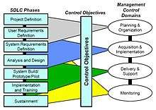
The SDLC phases serve as a programmatic guide to project activity and provide a flexible but consistent way to conduct projects to a depth matching the scope of the project. Each of the SDLC phase objectives are described in this section with key deliverables, a description of recommended tasks, and a summary of related control objectives for effective management. It is critical for the project manager to establish and monitor control objectives during each SDLC phase while executing projects. Control objectives help to provide a clear statement of the desired result or purpose and should be used throughout the entire SDLC process. Control objectives can be grouped into major categories (domains), and relate to the SDLC phases as shown in the figure.[16]
To manage and control any SDLC initiative, each project will be required to establish some degree of a work breakdown structure (WBS) to capture and schedule the work necessary to complete the project. The WBS and all programmatic material should be kept in the "project description" section of the project notebook. The WBS format is mostly left to the project manager to establish in a way that best describes the project work.
There are some key areas that must be defined in the WBS as part of the SDLC policy. The following diagram describes three key areas that will be addressed in the WBS in a manner established by the project manager.[16] The diagram shows coverage spans numerous phases of the SDLC but the associated MCD has a subset of primary mappings to the SDLC phases. For example, Analysis and Design is primarily performed as part of the Acquisition and Implementation Domain and System Build and Prototype is primarily performed as part of delivery and support.
Work breakdown structured organization
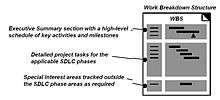
The upper section of the work breakdown structure (WBS) should identify the major phases and milestones of the project in a summary fashion. In addition, the upper section should provide an overview of the full scope and timeline of the project and will be part of the initial project description effort leading to project approval. The middle section of the WBS is based on the seven systems development life cycle phases as a guide for WBS task development. The WBS elements should consist of milestones and "tasks" as opposed to "activities" and have a definitive period (usually two weeks or more). Each task must have a measurable output (e.x. document, decision, or analysis). A WBS task may rely on one or more activities (e.g. software engineering, systems engineering) and may require close coordination with other tasks, either internal or external to the project. Any part of the project needing support from contractors should have a statement of work (SOW) written to include the appropriate tasks from the SDLC phases. The development of a SOW does not occur during a specific phase of SDLC but is developed to include the work from the SDLC process that may be conducted by external resources such as contractors.[16]
Baselines
Baselines are an important part of the systems development life cycle. These baselines are established after four of the five phases of the SDLC and are critical to the iterative nature of the model .[17] Each baseline is considered as a milestone in the SDLC.
- functional baseline: established after the conceptual design phase.
- allocated baseline: established after the preliminary design phase.
- product baseline: established after the detail design and development phase.
- updated product baseline: established after the production construction phase.
Complementary methodologies
Complementary software development methods to systems development life cycle are:
- Software prototyping
- Joint applications development (JAD)
- Rapid application development (RAD)
- Extreme programming (XP);
- Open-source development
- End-user development
- Object-oriented programming
| SDLC | RAD | Open source | Objects | JAD | Prototyping | End User | |
|---|---|---|---|---|---|---|---|
| Control | Formal | MIS | Weak | Standards | Joint | User | User |
| Time frame | Long | Short | Medium | Any | Medium | Short | Short
– |
| Users | Many | Few | Few | Varies | Few | One or two | One |
| MIS staff | Many | Few | Hundreds | Split | Few | One or two | None |
| Transaction/DSS | Transaction | Both | Both | Both | DSS | DSS | DSS |
| Interface | Minimal | Minimal | Weak | Windows | Crucial | Crucial | Crucial |
| Documentation and training | Vital | Limited | Internal | In Objects | Limited | Weak | None |
| Integrity and security | Vital | Vital | Unknown | In Objects | Limited | Weak | Weak |
| Reusability | Limited | Some | Maybe | Vital | Limited | Weak | None |
Strengths and weaknesses
Few people in the modern computing world would use a strict waterfall model for their SDLC as many modern methodologies have superseded this thinking. Some will argue that the SDLC no longer applies to models like Agile computing, but it is still a term widely in use in technology circles. The SDLC practice has advantages in traditional models of systems development that lends itself more to a structured environment. The disadvantages to using the SDLC methodology is when there is need for iterative development or (i.e. web development or e-commerce) where stakeholders need to review on a regular basis the software being designed.
A comparison of the strengths and weaknesses of SDLC:
| Strengths | Weaknesses |
|---|---|
| Control | Increased development time |
| Monitor large projects | Increased development cost |
| Detailed steps | Systems must be defined up front |
| Evaluate costs and completion targets | Rigidity |
| Documentation | Hard to estimate costs, project overruns |
| Well defined user input | User input is sometimes limited |
| Ease of maintenance | Little parallelism |
| Development and design standards | Automation of documentation and standards is limited |
| Tolerates changes in MIS staffing | Does not tolerate changes in requirements |
| Projects canned early result in little or no value |
An alternative to the SDLC is rapid application development, which combines prototyping, joint application development and implementation of CASE tools. The advantages of RAD are speed, reduced development cost, and active user involvement in the development process.
System lifecycle
The system lifecycle in systems engineering is a view of a system or proposed system that addresses all phases of its existence to include system conception, design and development, production and/or construction, distribution, operation, maintenance and support, retirement, phase-out and disposal.[19]
Conceptual design
The conceptual design stage is the stage where an identified need is examined, requirements for potential solutions are defined, potential solutions are evaluated and a system specification is developed. The system specification represents the technical requirements that will provide overall guidance for system design. Because this document determines all future development, the stage cannot be completed until a conceptual design review has determined that the system specification properly addresses the motivating need.
Key steps within the conceptual design stage include:
- Need identification
- Feasibility analysis
- System requirements analysis
- System specification
- Conceptual design review
Preliminary system design
During this stage of the system lifecycle, subsystems that perform the desired system functions are designed and specified in compliance with the system specification. Interfaces between subsystems are defined, as well as overall test and evaluation requirements.[20] At the completion of this stage, a development specification is produced that is sufficient to perform detailed design and development.
Key steps within the preliminary design stage include:
- Functional analysis
- Requirements allocation
- Detailed trade-off studies
- Synthesis of system options
- Preliminary design of engineering models
- Development specification
- Preliminary design review
For example, as the system analyst of Viti Bank, you have been tasked to examine the current information system. Viti Bank is a fast growing bank in Fiji. Customers in remote rural areas are finding difficulty to access the bank services. It takes them days or even weeks to travel to a location to access the bank services. With the vision of meeting the customers needs, the bank has requested your services to examine the current system and to come up with solutions or recommendations of how the current system can be provided to meet its needs.
Detail design and development
This stage includes the development of detailed designs that brings initial design work into a completed with form of specifications. This work includes the specification of interfaces between the system and its intended environment and a comprehensive evaluation of the systems logistical, maintenance and support requirements. The detail design and development is responsible for producing the product, process and material specifications and may result in substantial changes to the development specification.
Key steps within the detail design and development stage include:
- Detailed design
- Detailed synthesis
- Development of engineering and prototype models
- Revision of development specification
- Product, process and material specification
- Critical design review
Production and construction
During the production and/or construction stage the product is built or assembled in accordance with the requirements specified in the product, process and material specifications and is deployed and tested within the operational target environment. System assessments are conducted in order to correct deficiencies and adapt the system for continued improvement.
Key steps within the product construction stage include:
- Production and/or construction of system components
- Acceptance testing
- System distribution and operation
- Operational testing and evaluation
- System assessment
Utilization and support
Once fully deployed, the system is used for its intended operational role and maintained within its operational environment.
Key steps within the utilization and support stage include:
- System operation in the user environment
- Change management
- System modifications for improvement
- System assessment
Phase-out and disposal
Effectiveness and efficiency of the system must be continuously evaluated to determine when the product has met its maximum effective lifecycle[21]. Considerations include: Continued existence of operational need, matching between operational requirements and system performance, feasibility of system phase-out versus maintenance, and availability of alternative systems.
See also
References
- ↑ SELECTING A DEVELOPMENT APPROACH. Retrieved 17 July 2014.
- ↑ Parag C. Pendharkara; James A. Rodgerb; Girish H. Subramanian (November 2008). "An empirical study of the Cobb–Douglas production function properties of software development effort". Information and Software Technology. 50 (12): 1181–1188. doi:10.1016/j.infsof.2007.10.019.
- ↑ "Systems Development Life Cycle from". FOLDOC. Retrieved 2013-06-14.
- ↑ Software Development Life Cycle (SDLC), PowerPoint – Powered by Google Docs
- ↑ James Taylor (2004). Managing Information Technology Projects. p.39.
- 1 2 Geoffrey Elliott & Josh Strachan (2004) Global Business Information Technology. p.87.
- 1 2 3 4 US Department of Justice (2003). INFORMATION RESOURCES MANAGEMENT Chapter 1. Introduction.
- 1 2 3 Everatt, G.D.; McLeod Jr., R. (2007). "Chapter 2: The Software Development Life Cycle". Software Testing: Testing Across the Entire Software Development Life Cycle. John Wiley & Sons. pp. 29–58. ISBN 9780470146347.
- ↑ Unhelkar, B. (2016). The Art of Agile Practice: A Composite Approach for Projects and Organizations. CRC Press. pp. 56–59. ISBN 9781439851197.
- ↑ Land, S.K.; Smith, D.B.; Walz, J.W. (2012). Practical Support for Lean Six Sigma Software Process Definition: Using IEEE Software Engineering Standards. John Wiley & Sons. pp. 341–3. ISBN 9780470289952.
- ↑ Kay, Russell (May 14, 2002). "QuickStudy: System Development Life Cycle". ComputerWorld.
- ↑ Taylor, G.D. (2008). Introduction to Logistics Engineering. CRC Press. pp. 12.6–12.18. ISBN 9781420088571.
- ↑ Control and Audit, Information Systems. SDLC (August 2013 ed.). Chapter 5: Institute of Chartered Accountants of India. p. 5.28.
- ↑ Radack, S. (n.d.). "The system development life cycle (SDLC)" (PDF). National Institute of Standards and Technology.
- ↑ Marakas, James A. O'Brien, George M. (2010). Management information systems (10th ed.). New York: McGraw-Hill/Irwin. pp. 485–489. ISBN 0073376817.
- 1 2 3 4 5 U.S. House of Representatives (1999). Systems Development Life-Cycle Policy. p.13.
- ↑ Blanchard, B. S., & Fabrycky, W. J.(2006) Systems engineering and analysis (4th ed.) New Jersey: Prentice Hall. p.31
- 1 2 Post, G., & Anderson, D., (2006). Management information systems: Solving business problems with information technology. (4th ed.). New York: McGraw-Hill Irwin.
- ↑ Blanchard and Fabrycky (2006). Systems Engineering and Analysis, Fourth Edition. Prentice Hall. p. 19.
- ↑ Dr. Joahn Gouws (2007). Introduction to Engineering, System Engineering. Melikon Pty Ltd.
- ↑ Cunningham, James. "HERC Maintenance". Fargo. XXI (North Avenue): 49. Retrieved 13 May 2009.
Further reading
- Cummings, Haag (2006). Management Information Systems for the Information Age. Toronto, McGraw-Hill Ryerson
- Beynon-Davies P. (2009). Business Information Systems. Palgrave, Basingstoke. ISBN 978-0-230-20368-6
- Computer World, 2002, Retrieved on June 22, 2006 from the World Wide Web:
- Management Information Systems, 2005, Retrieved on June 22, 2006 from the World Wide Web:
- This article is based on material taken from the Free On-line Dictionary of Computing prior to 1 November 2008 and incorporated under the "relicensing" terms of the GFDL, version 1.3 or later.
External links
| Wikimedia Commons has media related to Systems Development Life Cycle. |
- The Agile System Development Lifecycle
- Pension Benefit Guaranty Corporation – Information Technology Solutions Lifecycle Methodology
- FSA Life Cycle Framework
- HHS Enterprise Performance Life Cycle Framework
- The Open Systems Development Life Cycle
- System Development Life Cycle Evolution Modeling
- Zero Deviation Life Cycle
- Integrated Defense AT&L Life Cycle Management Chart, the U.S. DoD form of this concept.