Surge protector
A surge protector (or spike suppressor or surge suppressor or surge diverter[1]) is an appliance or device designed to protect electrical devices from voltage spikes.
Overview
A voltage spike is a transient event, typically lasting 1 to 30 microseconds, that may reach over 1000 volts. Lightning that hits a power line can give many thousands, sometimes 100,000 or more volts. A motor when switched off can generate a spike of 1000 or more volts. Spikes can degrade wiring insulation and destroy electronic devices like battery chargers, modems and TVs.
Spikes can also occur on telephone and data lines when AC mains lines accidentally connect to them or lightning hits them or the telephone and data lines travel near to lines with a spike and the voltage is induced.
A long term surge, lasting seconds, minutes, or hours, caused by power transformer failures such as a lost neutral or other power company error, are not protected by transient protectors. Long term surges can destroy the protectors in an entire building or area. Even 10s of milliseconds can be longer than a protector can handle. Long term surges may or may not be handled by fuses and over voltage relays.
A transient surge protector attempts to limit the voltage supplied to an electric device by either blocking or shorting current to reduce the voltage below a safe threshold. Blocking is done by using inductors which inhibit a sudden change in current. Shorting is done by spark gaps, discharge tubes, zener-type semiconductors, and MOVs (Metal Oxide Varistors), all of which begin to conduct current once a certain voltage threshold is reached, or by capacitors which inhibit a sudden change in voltage. Some surge protectors use multiple elements.
The most common and effective way is the shorting method in which the electrical lines are temporarily shorted together until the voltage is reduced by the resistance in the power lines. The spike's energy is dissipated in the power lines (and/or the ground), converted to heat. Since a spike lasts only 10s of microseconds, the temperature rise is minimal. However, if the spike is large enough, like a nearby hit by lightning, there might not be enough power line or ground resistance and the MOV (or other protection element) can be destroyed and power lines melted.
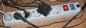
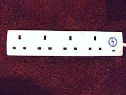
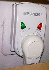
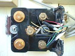
Surge protectors for homes can be in power strips used inside, or a device outside at the power panel. A modern house has three wires, Line, Neutral, and Ground (L,N, and G). Many protectors will connect to all three, in pairs, L-N,L-G,and N-G, since there are conditions, like lightning, where both L and N have high voltage spikes that need to be shorted to ground.
Definitions
The terms surge protection device (SPD) and transient voltage surge suppressor (TVSS) are used to describe electrical devices typically installed in power distribution panels, process control systems, communications systems, and other heavy-duty industrial systems, for the purpose of protecting against electrical surges and spikes, including those caused by lightning. Scaled-down versions of these devices are sometimes installed in residential service entrance electrical panels, to protect equipment in a household from similar hazards.[2]
Many power strips have basic surge protection built in; these are typically clearly labeled as such. However, in unregulated countries there are power strips labelled as "surge" or "spike" protectors that only have a capacitor or RFI circuit (or nothing) that do not provide true (or any) spike protection.
Important specifications
These are some of the most prominently featured specifications which define a surge protector for AC mains, as well as for some data communications protection applications.
Clamping voltage
Also known as the let-through voltage, this specifies what spike voltage will cause the protective components inside a surge protector to short or clamp.[3] A lower clamping voltage indicates better protection, but can sometimes result in a shorter life expectancy for the overall protective system. The lowest three levels of protection defined in the UL rating are 330 V, 400 V and 500 V. The standard let-through voltage for 120 V AC devices is 330 volts.[4]
Underwriters Laboratories (UL),[5] a global independent safety science company, defines how a protector may be used safely. UL 1449 became compliance mandatory with the 3rd edition in September 2009 to increase safety compared to products conforming to the 2nd edition. A measured limiting voltage test, using six times higher current (and energy), defines a voltage protection rating (VPR). For a specific protector, this voltage may be higher compared to a Suppressed Voltage Ratings (SVR) in previous editions that measured let-through voltage with less current. Due to non-linear characteristics of protectors, let-through voltages defined by 2nd edition and 3rd edition testing are not comparable.[4][6]
A protector may be larger to obtain a same let-through voltage during 3rd edition testing. Therefore, a 3rd edition or later protector should provide superior safety with increased life expectancy.
A protector with a higher let-through voltage, e.g.400v vs 330v, will pass a higher voltage to the connected device. The design of the connected device determines whether this pass-thorough spike will cause damage. Motors and mechanical devices are usually not affected. Some (especially older) electronic parts, like chargers, LED or CFL bulbs and computerized appliances are sensitive and can be compromised and have their life reduced.
Joule rating
The Joule rating number defines how much energy a MOV-based surge protector can theoretically absorb in a single event, without failure. Better protectors exceed ratings of 1000 joules and 40,000 amperes. Since the actual duration of a spike is only about 10 microseconds, the actual power dissipated in the MOV is only 1 to 20 watts. Any more than that and the MOV will fuse, or sometimes short and melt, hopefully blowing a fuse, disconnecting itself from the circuit.
The MOV (or other shorting device) requires resistance in the supply line in order to limit the voltage. If you have big, low resistance, power lines you need a bigger, larger joule rated MOV. Inside a house, with smaller wires that have more resistance, you can use lower ratings.
Every time a MOV shorts, its internal structure is changed and its threshold voltage reduced slightly. After many spikes the threshold voltage can reduce enough to be near the line voltage, i.e. 120 vac or 240 vac. At this point the MOV will partially conduct and heat up and eventually fail, sometimes in a dramatic meltdown or even a fire. Most modern surge protectors have circuit breakers and temperature fuses to prevent serious consequences. Many also have a LED light to indicate if the MOVs are still functioning.
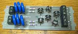
The joule rating is commonly quoted for comparing MOV-based surge protectors. An average surge (spike) is of short duration, lasting for nanoseconds to microseconds, and experimentally modeled surge energy can be less than 100 joules.[7] Well-designed surge protectors consider the resistance of the lines that supply the power, the chance of lightning or other seriously energetic spike, and specify the MOVs accordingly. A little battery charger might include a MOV of only 1 watt, whereas a surge strip will have a 20 watt MOV or several of them in parallel. A house protector will have a large block-type MOV.
Some manufacturers commonly design higher joule-rated surge protectors by connecting multiple MOVs in parallel and this can produce a misleading rating. Since individual MOVs have slightly different voltage thresholds and non-linear responses when exposed to the same voltage curve, any given MOV might be more sensitive than others. This can cause one MOV in a group to conduct more (a phenomenon called current hogging), leading to possible overuse and eventual premature failure of that component. However the other MOVs in the group do help a little as they start to conduct as the voltage continues to rise as it does since a MOV does not have a sharp threshold. It may start to short at 270 volts but not reach full short until 450 or more volts. A second MOV might start at 290 volts and another at 320 volts so they all can help clamp the voltage, and at full current there is a series ballast effect that improves current sharing, but stating the actual joule rating as the sum of all the individual MOVs does not accurately reflect the total clamping ability. The first MOV may bear more of the burden and fail earlier. One MOV manufacturer recommends using fewer but bigger MOVs (e.g.60mm vs 40mm diameter) if they can fit in the device and to match them and derate them. In some cases it may take four 40 mm MOVs to be equivalent to one 60 mm MOV.[8]
A further problem is that if a single inline fuse is placed in series with a group of paralleled MOVs as a disconnect safety feature, it will open and disconnect all remaining working MOVs.
The effective surge energy absorption capacity of the entire system is dependent on the MOV matching so derating by 20% or more is usually required. This limitation can be managed by using carefully matched sets of MOVs, matched according to manufacturer's specification.[9][8]
According to industry testing standards, based on IEEE and ANSI assumptions, power line surges inside a building can be up to 6,000 volts and 3,000 amperes, and deliver up to 90 joules of energy, including surges from external sources not including lightning strikes.
The common assumptions regarding lightning specifically, based ANSI/IEEE C62.41 and UL 1449 (3rd Edition) at time of this writing, are that minimum lightning-based power line surges inside a building are typically 10,000 amperes or 10 kiloamperes (kA). This is based on 20 kA striking a power line, the imparted current then traveling equally in both directions on the power line with the resulting 10 kA traveling into the building or home. These assumptions are based on an average approximation for testing minimum standards. While 10 kA is typically good enough for minimum protection against lightning strikes it is possible for a lightning strike to impart up to 200 kA to a power line with 100 kA traveling in each direction.
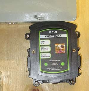
Lightning and other high-energy transient voltage surges can be suppressed with pole mounted supressors by the utility, or with an owner supplied whole house surge protector. A whole house product is more expensive than simple single-outlet surge protectors and often needs professional installation on the incoming electrical power feed; however, they prevent power line spikes from entering the house. Damage from direct lightning strikes via other paths must be controlled separately.
Response time
Surge protectors don't operate instantaneously; a slight delay exists, some few nanoseconds. The longer the response time and depending on system impedance, the connected equipment maybe exposed to some of the surge. However, surges typically are much slower and take around a few microseconds to reach their peak voltage, and a surge protector with a nanosecond response time would kick in fast enough to suppress the most damaging portion of the spike.[10]
Thus response time under standard testing is not a useful measure of a surge protector's ability when comparing MOV devices. All MOVs have response times measured in nanoseconds, while test waveforms usually used to design and calibrate surge protectors are all based on modeled waveforms of surges measured in microseconds. As a result, MOV-based protectors have no trouble producing impressive response-time specs.
Slower-responding technologies (notably, GDTs) may have difficulty protecting against fast spikes. Therefore, good designs incorporating slower but otherwise useful technologies usually combine them with faster-acting components, to provide more comprehensive protection.[11]
Standards
Some frequently listed standards include:
- IEC 61643-11 Low-voltage surge protective devices - Part 11: Surge protective devices connected to low-voltage power systems - Requirements and test methods (replaces IEC 61643-1)
- IEC 61643-21 Low voltage surge protective devices - Part 21: Surge protective devices connected to telecommunications and signalling networks - Performance requirements and testing methods
- IEC 61643-22 Low-voltage surge protective devices - Part 22: Surge protective devices connected to telecommunications and signalling networks - Selection and application principles
- EN 61643-11, 61643-21 and 61643-22
- Telcordia Technologies Technical Reference TR-NWT-001011
- ANSI/IEEE C62.xx
- Underwriters Laboratories (UL) 1449.
- AS/NZS 1768
Each standard defines different protector characteristics, test vectors, or operational purpose.
The 3rd Edition of UL Standard 1449 for SPDs was a major rewrite of previous editions, and was also accepted as an ANSI standard for the first time.[12][13] A subsequent revision in 2015 included the addition of low-voltage circuits for USB charging ports and associated batteries. [14][15]
EN 62305 and ANSI/IEEE C62.xx define what spikes a protector might be expected to divert. EN 61643-11 and 61643-21 specify both the product's performance and safety requirements. In contrast, the IEC only writes standards and does not certify any particular product as meeting those standards. IEC Standards are used by members of the CB Scheme of international agreements to test and certify products for safety compliance.
None of those standards guarantee that a protector will provide proper protection in a given application. Each standard defines what a protector should do or might accomplish, based on standardized tests that may or may not correlate to conditions present in a particular real-world situation. A specialized engineering analysis may be needed to provide sufficient protection, especially in situations of high lightning risk.
Primary components
Systems used to reduce or limit high-voltage surges[16][17] can include one or more of the following types of electronic components. Some surge suppression systems use multiple technologies, since each method has its strong and weak points.[11][18][19] The first six methods listed operate primarily by diverting unwanted surge energy away from the protected load, through a protective component connected in a parallel (or shunted) topology. The last two methods also block unwanted energy by using a protective component connected in series with the power feed to the protected load, and additionally may shunt the unwanted energy like the earlier systems.
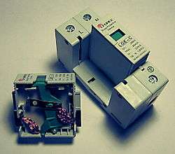
Metal oxide varistor
A metal oxide varistor (MOV) consists of a bulk semiconductor material (typically sintered granular zinc oxide) that can conduct large currents (effectively short-circuits) when presented with a voltage above its rated voltage.[4][20] MOVs typically limit voltages to about 3 to 4 times the normal circuit voltage by diverting surge current elsewhere than the protected load. MOVs may be connected in parallel to increase current capability and life expectancy, providing they are matched sets. (Unmatched MOVs have a tolerance of approximately ±10% on voltage ratings, which may not be sufficient [8].) For more details on the effectiveness of parallel-connected MOVs, see the section on Joules rating elsewhere in this article.
MOVs have finite life expectancy and "degrade" when exposed to a few large transients, or many small transients.[21][22]. Every time a MOV activates (shorts,) its threshold voltage reduces slightly. After many spikes the threshold voltage can reduce enough to be near the protection voltage, either mains or data. At this point the MOV conducts more and more often, heats up and finally fails. In data circuits, the data channel becomes shorted and non-functional. In a power circuit, you may get a dramatic meltdown or even a fire if not protected by a fuse of some kind. [23].
Most modern surge strips and house protectors have circuit breakers and temperature fuses to prevent serious consequences. A thermal fuse disconnects the MOV when it gets too hot. Only the MOV is disconnected leaving the rest of the circuit working but not protected. Often there is a LED light to indicate if the MOVs are still functioning. Older surge strips had no thermal fuse and relied on a 10 or 15 amp circuit breaker which usually blew only after the MOVs had smoked, burned, popped, melted and permanently shorted.
A failing MOV is a fire risk, which is a reason for the National Fire Protection Association's (NFPA)[24] UL1449 in 1986[25] and subsequent revisions in 1998, 2009 and 2015. NFPA's primary concern is protection from fire. .[4][26]
Therefore, all MOV-based protectors intended for long-term use should have an indicator that the protective components have failed, and this indication must be checked on a regular basis to ensure that protection is still functioning.[27]
Because of their good price/performance ratio, MOVs are the most common protector component in low-cost basic AC power protectors.
Transient voltage suppression (TVS) diode
A TVS diode is a type of Zener diode, also called an avalanche diode or silicon avalanche diode (SAD), which can limit voltage spikes. These components provide the fastest limiting action of protective components (theoretically in picoseconds), but have a relatively low energy-absorbing capability. Voltages can be clamped to less than twice the normal operation voltage. If current impulses remain within the device ratings, life expectancy is exceptionally long. If component ratings are exceeded, the diode may fail as a permanent short circuit; in such cases, protection may remain but normal circuit operation is terminated in the case of low-power signal lines. Due to their relatively limited current capacity, TVS diodes are often restricted to circuits with smaller current spikes. TVS diodes are also used where spikes occur significantly more often than once a year, since this component will not degrade when used within its ratings. A unique type of TVS diode (trade names Transzorb or Transil) contains reversed paired series avalanche diodes for bi-polar operation.
TVS diodes are often used in high-speed but low-power circuits, such as occur in data communications. These devices can be paired in series with another diode to provide low capacitance[28] as required in communication circuits.
Thyristor surge protection device (TSPD)
A Trisil is a type of thyristor surge protection device (TSPD), a specialized solid-state electronic device used in crowbar circuits to protect against overvoltage conditions. A SIDACtor is another thyristor type device used for similar protective purposes.
These thyristor-family devices can be viewed as having characteristics much like a spark gap or a GDT, but can operate much faster. They are related to TVS diodes, but can "break over" to a low clamping voltage analogous to an ionized and conducting spark gap. After triggering, the low clamping voltage allows large current surges while limiting heat dissipation in the device.
Gas discharge tube (GDT)
A gas discharge tube (GDT) is a sealed glass-enclosed device containing a special gas mixture trapped between two electrodes, which conducts electric current after becoming ionized by a high voltage spike.[29] GDTs can conduct more current for their size than other components. Like MOVs, GDTs have a finite life expectancy, and can handle a few very large transients or a greater number of smaller transients. The typical failure mode occurs when the triggering voltage rises so high that the device becomes ineffective, although lightning surges can occasionally cause a dead short.
GDTs take a relatively long time to trigger, permitting a higher voltage spike to pass through before the GDT conducts significant current. It is not uncommon for a GDT to let through pulses of 500 V or more of 100 ns in duration. In some cases, additional protective components are necessary to prevent damage to a protected load, caused by high-speed let-through voltage which occurs before the GDT begins to operate.
GDTs create an effective short circuit when triggered, so that if any electrical energy (spike, signal, or power) is present, the GDT will short this. Once triggered, a GDT will continue conducting (called follow-on current) until all electric current sufficiently diminishes, and the gas discharge quenches. Unlike other shunt protector devices, a GDT once triggered will continue to conduct at a voltage less than the high voltage that initially ionized the gas; this behavior is called negative resistance. Additional auxiliary circuitry may be needed in DC (and some AC) applications to suppress follow-on current, to prevent it from destroying the GDT after the initiating spike has dissipated. Some GDTs are designed to deliberately short out to a grounded terminal when overheated, thereby triggering an external fuse or circuit breaker.[30]
Many GDTs are light-sensitive, in that exposure to light lowers their triggering voltage. Therefore, GDTs should be shielded from light exposure, or opaque versions that are insensitive to light should be used.
The CG2 SN series of surge arrestors, formerly produced by C P Clare, are advertised as being non-radioactive, and the datasheet for that series states that some members of the CG/CG2 series (75-470V) are radioactive. [31]
Due to their exceptionally low capacitance, GDTs are commonly used on high frequency lines, such as those used in telecommunications equipment. Because of their high current-handling capability, GDTs can also be used to protect power lines, but the follow-on current problem must be controlled.
Selenium voltage suppressor
An "overvoltage clamping" bulk semiconductor similar to an MOV, though it does not clamp as well. However, it usually has a longer life than an MOV. It is used mostly in high-energy DC circuits, like the exciter field of an alternator. It can dissipate power continuously, and it retains its clamping characteristics throughout the surge event, if properly sized.
Carbon block spark gap overvoltage suppressor
A spark gap is one of the oldest protective electrical technologies still found in telephone circuits, having been developed in the nineteenth century. A carbon rod electrode is held with an insulator at a specific distance from a second electrode. The gap dimension determines the voltage at which a spark will jump between the two parts and short to ground. The typical spacing for telephone applications in North America is 0.076 mm (0.003 inches).[32] Carbon block suppressors are similar to gas arrestors (GDTs) but with the two electrodes exposed to the air, so their behavior is affected by the surrounding atmosphere, especially the humidity. Since their operation produces an open spark, these devices should never be installed where an explosive atmosphere may develop.
Quarter-wave coaxial surge arrestor
Used in RF signal transmission paths, this technology features a tuned quarter-wavelength short-circuit stub that allows it to pass a bandwidth of frequencies, but presents a short to any other signals, especially down towards DC. The passbands can be narrowband (about ±5% to ±10% bandwidth) or wideband (above ±25% to ±50% bandwidth). Quarter-wave coax surge arrestors have coaxial terminals, compatible with common coax cable connectors (especially N or 7-16 types). They provide the most rugged available protection for RF signals above 400 MHz; at these frequencies they can perform much better than the gas discharge cells typically used in the universal/broadband coax surge arrestors. Quarter-wave arrestors are useful for telecommunications applications, such as Wi-Fi at 2.4 or 5 GHz but less useful for TV/CATV frequencies. Since a quarter-wave arrestor shorts out the line for low frequencies, it is not compatible with systems which send DC power for a LNB up the coaxial downlink.
Series mode (SM) surge suppressors
These devices are not rated in joules because they operate differently from the earlier suppressors, and they do not depend on materials that inherently wear out during repeated surges. SM suppressors are primarily used to control transient voltage surges on electrical power feeds to protected devices. They are essentially heavy-duty low-pass filters connected so that they allow 50 or 60 Hz line voltages through to the load, while blocking and diverting higher frequencies. This type of suppressor differs from others by using banks of inductors, capacitors and resistors that suppress voltage surges and inrush current to the neutral wire, whereas other designs shunt to the ground wire.[33] Surges are not diverted but actually suppressed. The inductors slow down the energy. Since the inductor in series with the circuit path slows the current spike, the peak surge energy is spread out in the time domain and harmlessly absorbed and slowly released from a capacitor bank.[34]
Experimental results show that most surge energies occur at under 100 joules, so exceeding the SM design parameters is unlikely. SM suppressors do not present a fire risk should the absorbed energy exceed design limits of the dielectric material of the components because the surge energy is also limited via arc-over to ground during lightning strikes, leaving a surge remnant that often does not exceed a theoretical maximum (such as 6000 V at 3000 A with a modeled shape of 8 × 20 microsecond waveform specified by IEEE/ANSI C62.41). Because SMs work on both the current rise and the voltage rise, they can safely operate in the worst surge environments.
SM suppression focuses its protective philosophy on a power supply input, but offers nothing to protect against surges appearing between the input of an SM device and data lines, such as antennae, telephone or LAN connections, or multiple such devices cascaded and linked to the primary devices. This is because they do not divert surge energy to the ground line. Data transmission requires the ground line to be clean in order to be used as a reference point. In this design philosophy, such events are already protected against by the SM device before the power supply. NIST reports that "Sending them [surges] down the drain of a grounding conductor only makes them reappear within a microsecond about 200 meters away on some other conductor."[35] So having protection on a data transmission line is only required if surges are diverted to the ground line.
In comparison to devices relying on 10-cent components that operate only briefly (such as MOVs or GDTs), SM devices tend to be bulkier and heavier than those simpler spike shunting components. The initial costs of SM filters are higher, typically 130 USD and up, but a long service life can be expected if they are used properly. In-field installation costs can be higher, since SM devices are installed in series with the power feed, requiring the feed to be cut and reconnected.
See also
References
- ↑ Energy Safe Victoria. "Safety switches, surge diverters and circuit breakers". Gas and electrical safety in the home. Energy Safe Victoria. Archived from the original on 2016-05-10. Retrieved 2016-05-04.
- ↑ NIST. "Coordination of cascaded surge-protective devices". Surge Protection in Low-Voltage AC Power Circuits: An 8-part Anthology. NIST. Retrieved 2013-11-08.
- ↑ "Terms C". grouper.IEEE.org. Archived from the original on 3 March 2016. Retrieved 18 January 2018.
- 1 2 3 4 Rosch, Winn (May 2008). "UL® 1449 3rd Edition" (PDF). Eaton Corporation. Eaton Corporation. Retrieved 12 March 2016.
- ↑ "About UL - UL". UL.com. 18 July 2014. Retrieved 18 January 2018.
- ↑ "UL 1449 Third Edition: SPD/TVSS Changes Effective September 29, 2009" (PDF).
- ↑ "No Joules for Surges: Relevant and Realistic Assessment of Surge Stress Threats" (PDF). NIST.gov. Archived from the original (PDF) on 2013-02-25. Retrieved 18 January 2018.
- 1 2 3 "Walaszczyk, et al. 2001 "Does Size Really Matter? An Exploration of ... Paralleling Multiple Lower Energy Movs"" (PDF). Littelfuse.com. Retrieved 18 January 2018.
- ↑ Littelfuse, Inc. "EC638 - Littelfuse Varistor Design Examples" (PDF). Littelfuse, Inc. Retrieved 2011-03-29. See pages 7-8, "Parallel Operation of Varistors"
- ↑ "Terms R". grouper.IEEE.org. Archived from the original on 9 April 2017. Retrieved 18 January 2018.
- 1 2 Littelfuse, Inc. "EC640 - Combining GDTs and MOVs for Surge Protection of AC Lines" (PDF). Littelfuse, Inc. Retrieved 2011-03-29.
- ↑ Eaton Corporation. "TD01005005E - UL 1449 3rd Edition - Key Changes" (PDF). Eaton Corporation. Archived from the original (PDF) on 2011-08-15. Retrieved 2011-03-29.
- ↑ Siemens AG. "Next Generation Surge Protection: UL 1449 Third Edition" (PDF). Siemens AG. Archived from the original (PDF) on 2011-07-21. Retrieved 2011-03-29.
- ↑ "Standard 1449 — Standard for Surge Protective Devices". UL LLC. Retrieved February 18, 2016.
- ↑ "UL Publishes New Edition of UL 1449". In Compliance Magazine. Retrieved February 18, 2016.
- ↑ Littelfuse, Inc. "AN9769 - An Overview of Electromagnetic and Lightning Induced Voltage Transients" (PDF). Littelfuse, Inc. Retrieved 2011-03-29.
- ↑ Littelfuse, Inc. "AN9768 - Transient Suppression Devices and Principles" (PDF). Littelfuse, Inc. Retrieved 2011-03-29.
- ↑ Circuit Components Inc. "Filtering and Surge Suppression Fundamentals" (PDF). Circuit Components Inc. Archived from the original (PDF) on 2010-12-13. Retrieved 2011-03-29. Includes extensive comparison of design tradeoffs among various surge suppression technologies.
- ↑ Underwriters Laboratories. "Application Guideline". UL 6500 - Second Edition. Archived from the original on 2011-07-16. Retrieved 2011-03-29. Connection of MOVs and GDTs in series
- ↑ Littelfuse, Inc. "AN9767 - Littelfuse Varistors: Basic Properties, Terminology and Theory" (PDF). Littelfuse, Inc. Retrieved 2011-03-29.
- ↑ Brown, Kenneth (March 2004). "Metal Oxide Varistor Degradation". IAEI Magazine. Archived from the original on 2011-07-19. Retrieved 2011-03-30.
- ↑ Walaszczyk, et al. 2001 "Does Size Really Matter? An Exploration of ... Paralleling Multiple Lower Energy Movs". See Figures 4 & 5 for Pulse Life Curves.
- ↑ "Application Note 9311 "The ABCs of MOVs". See "Q. How does an MOV fail?" on page 10-48" (PDF). Littelfuse.com. Retrieved 18 January 2018.
- ↑ "Archived copy". Archived from the original on 2012-02-12. Retrieved 2012-02-07.
- ↑
- ↑ "Archived copy". Archived from the original on 2007-03-16. Retrieved 2007-06-20.
- ↑ "Application Note 9773 "Varistor Testing" Jan 1998. See "Varistor Rating Assurance Tests" on page 10-145 for definition of "end-of-lifetime"" (PDF). Littelfuse.com. Retrieved 18 January 2018.
- ↑ SemTech "TVS Diode Application Note" Rev 9/2000. Archived 2009-01-12 at the Wayback Machine. See chart entitled "TVS Capacitance vs Transmission Rate".
- ↑ Citel Inc. "Gas Discharge Tube Overview". Archived from the original on March 5, 2012. Retrieved 2013-05-30.
- ↑ Sankosha. "Fail Safe Device". Retrieved 2011-03-28.
- ↑ "C P Clare datasheet".
- ↑ "Microsemi - Semiconductor & System Solutions - Power Matters" (PDF). www.Zarlink.com. Retrieved 18 January 2018.
- ↑ "Surge suppression computer definition". YourDictionary.com. Retrieved 18 January 2018.
- ↑ "How It Works - Brick Wall". Brick Wall. Retrieved 18 January 2018.
- ↑ Ibacache, Rodrigo (13 January 2009). "Surge Protection in Low-Voltage AC Power Circuits" (PDF). NIST.gov. Retrieved 18 January 2018.
External links
| Wikimedia Commons has media related to Surge protectors. |
- Surge protector at Curlie (based on DMOZ)
- Surge Protection in Low-Voltage AC Power Circuits: An 8-part Anthology A comprehensive compilation of papers and articles published 1963-2003, hosted by the National Institute of Standards and Technology (NIST), an agency of the US Commerce Department.
- NEMA Surge Protection Institute