ReGIS
ReGIS, short for Remote Graphic Instruction Set, was a vector graphics markup language developed by Digital Equipment Corporation (DEC) for later models of their famous VT series of computer terminals. ReGIS supported rudimentary vector graphics consisting of lines, circular arcs, and similar shapes. Terminals supporting ReGIS generally allowed graphics and text to be mixed on-screen, which made construction of graphs and charts relatively easy.
History
ReGIS was first introduced on the VT125 in July 1981, followed shortly thereafter by the VK100 "GIGI" which combined the VT125 display system with composite video output and a BASIC interpreter. Later versions of the VT series included ReGIS, often with color support as well. This included the VT240 and 241 and the VT330 and 340. ReGIS is also supported by a small number of terminal emulator systems.
ReGIS replaced an earlier system known as waveform graphics that had been introduced on the VT55 and later used on the VT105. DEC normally provided backward compatibility with their terminals, but in this case the waveform system was simply dropped when ReGIS was introduced.
Description
ReGIS consisted of five primary drawing commands and a selection of status and device control commands. ReGIS mode was entered by specifying the escape code sequence ESCP0p, and exited with ESC\. The sequence ESCP is the generic Device Control String (DCS) used in the VT series of terminals, and is also used for a variety of other commands. The digit following the DCS was optional and specified a mode, in this case mode 0. Mode 0 was the default and picked up drawing where it left off, 1 reset the system to a blank slate, and 2 and 3 were the same as 0 and 1, but left a single line of text at the bottom of the screen for entering commands.
All drawing was based on an active pen location. Any command that moved the pen left it there for the next operation, similar to the operation of a mechanical plotter. The coordinate system was 0 to 799 in the X axis, and 0 to 479 in Y, with 0,0 in the upper left. In early implementations such as the VK100 and VT125, the actual device resolution was only 240 pixels, so the Y coordinates were "folded" so odd and even coordinates were the same location on the screen, but the VT240 and VT241 provided the full 480 pixel vertical resolution. The coordinate system could also be set by the user.
Coordinates could be pushed or pulled from a stack, and every command allowed the stack to be used as a parameter, the "b" parameter pushed the current coordinates on the stack, "e" popped it back off again. Coordinates could be specified in absolute or relative terms;
[200,100] is an absolute position at x=200, y=100
[+200,-100] is a relative position at x=current X+200, y=current Y-100
[200] is absolute x=200, y=unchanged (same as [200,+0])
[,-100] is relative, x=unchanged, y=current Y-100
There were four main drawing commands and three control commands;
P "Position", move the pen
V "Vector", draw a line
C "Curve", draw a circle (C) or arc (A)
F "Fill", draws a filled polygon
T "Text", output the following string of text
S "Screen", a catch-all command for setting a wide variety of modes
R "Report", outputs current status
W "Write", sets the pen parameters
L "Load", loads an alternate character set
@ "Macrograph", see below
Each of these commands used the various coordinate modes in different ways, and some had additional parameters that were enclosed in parentheses. Commands could be followed by one or more parameters, allowing continued drawing from a single command. The interpreter was not case sensitive.
Some ReGIS terminals supported color, using a series of registers. These could be set with the S command using a variety of color input styles. s(m3(r100g0b0)) sets color register ("map") 3 to "r"ed using the RGB color system, while s(m3(h120l50s100)) does the same using the HSV system. The W command likewise set a wide variety of different styles, mostly for masking, fills and brushes.
Finally, ReGIS allowed commands to be stored into a macrograph and then recalled using the @ operator. Up to 10,000 characters of code could be stored in the macros, each named with a single letter. The advantage was that the series of operations in the macro could be invoked by sending only two characters over the serial port, as opposed to the entire sequence of commands.
Sample
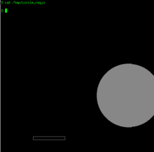
<ESC>P0p
S(E)(C1)
P[100,440]
V(B),[+100,+0],[+0,-10],[-100,+0],(E)
P[500,300],F(C[+100])
<ESC>\
This code enters ReGIS mode and uses the S command to erase the screen with (E) and then turns on the visible cursor with (C1). P[100,440] moves the pen to 100,440 absolute. V(B),[+100,+0],[+0,-10],[-100,+0],(E) draws a series of lines, first pushing the current pen location onto the stack with (B), then drawing three lines using relative coordinates, and then using (E) to pop the previously saved location off the stack and draw to it. The result is a rectangle 100 by 10 pixels in size.
P[500,300],F(C[+100]) then moves to a new location, and uses the "F"ill command to wrap a "C"ircle. The fill command could wrap any number of commands within its parentheses, allowing it to fill complex shapes. It also allowed the inclusion of a "temporary write" that allowed the programmer to set the fill style within the fill, and abandon it as soon as it ended.
See also
References
- "VT330/VT340 Programmer Reference Manual, Volume 2: Graphics Programming", Digital, EK-VT3XX-GP-002, 2nd Edition, May 1988
- "DEC ReGIS Graphics News", DEC Professional, August 1990, pg. 22