Quarter-wave impedance transformer
A quarter-wave impedance transformer, often written as λ/4 impedance transformer, is a component used in electrical engineering consisting of a length of transmission line or waveguide exactly one-quarter of a wavelength (λ) long and terminated in some known impedance. The device presents at its input the dual of the impedance with which it is terminated.
It is a similar concept to a stub; but whereas a stub is terminated in a short (or open) circuit and the length is chosen so as to produce the required impedance, the λ/4 transformer is the other way around; it is a pre-determined length and the termination is designed to produce the required impedance.
The relationship between the characteristic impedance, Z0, input impedance, Zin and load impedance, ZL is:

Applications
At radio frequencies of upper VHF or higher up to microwave frequencies one quarter wavelength is conveniently short enough to incorporate the component within many products, but not so small that it cannot be manufactured using normal engineering tolerances, and it is at these frequencies where the device is most often encountered. It is especially useful for making an inductor out of a capacitor, since designers have a preference for the latter.[1]
Another application is when DC power needs to be fed into a transmission line, which may be necessary to power an active device connected to the line, such as a switching transistor or a varactor diode for instance. An ideal DC voltage source has zero impedance, that is, it presents a short circuit and it is not useful to connect a short circuit directly across the line. Feeding in the DC via a λ/4 transformer will transform the short circuit into an open circuit which has no effect on the signals on the line.[2] Likewise, an open circuit can be transformed into a short circuit.[3]
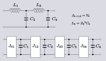
The device can be used as a component in a filter and in this application it is sometimes known as an inverter because it produces the mathematical inverse of an impedance. Impedance inverters are not to be confused with the more common meaning of power inverter for a device that has the inverse function of a rectifier. Inverter is a general term for the class of circuits that have the function of inverting an impedance. There are many such circuits and the term does not necessarily imply a λ/4 transformer. The most common use for inverters is to convert a 2-element-kind[4] LC filter design such as a ladder network into a one-element-kind filter. Equally, for bandpass filters, a two-resonator-kind (resonators and anti-resonators) filter can be converted to a one-resonator-kind. Inverters are classified as K-inverters or J-inverters[5] depending on whether they are inverting a series impedance or a shunt admittance.[1] Filters incorporating λ/4 inverters are only suitable for narrow band applications. This is because the impedance transformer line only has the correct electrical length of λ/4 at one specific frequency. The further the signal is from this frequency the less accurately the impedance transformer will be reproducing the impedance inverter function and the less accurately it will be representing the element values of the original lumped element filter design.[6]
Theory of operation
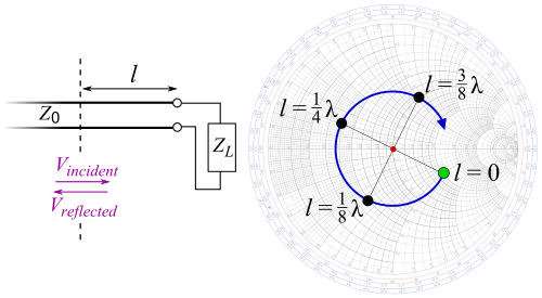
A transmission line that is terminated in some impedance, ZL, that is different from the characteristic impedance, Z0, will result in a wave being reflected from the termination back to the source. At the input to the line the reflected voltage adds to the incident voltage and the reflected current subtracts (because the wave is travelling in the opposite direction) from the incident current. The result is that the input impedance of the line (ratio of voltage to current) differs from the characteristic impedance and for a line of length l is given by;[7]
- where γ is the line propagation constant.

A very short transmission line, such as those being considered here, in many situations will have no appreciable loss along the length of the line and the propagation constant can be considered to be purely imaginary phase constant, iβ and the impedance expression reduces to,[7]

Since β is the same as the angular wavenumber,

for a quarter-wavelength line,


and the impedance becomes,taking the limit as the tangent function argument approaches


which is the same as the condition for dual impedances;
Notes
- 1 2 Matthaei et al, pp.144-149.
- ↑ Bhat & Koul, p.686.
- ↑ Bhat & Koul, pp.601-602.
- ↑ A 2-element-kind network is one consisting of only two kinds of elements, that is, LC, RC or RL circuits.
- ↑ The K and J notation originates in archaic symbols for impedance and admittance respectively. The K is the same K that makes an appearance in the well known constant-k filter and the K parameter is defined for inverters of lumped element design in exactly the same way as it is defined for the constant-k filter. For a λ/4 transformer the difference is moot, the same device will serve as a K-inverter with an inverter parameter of K=Z0 or equally as a J-inverter with an admittance inverter parameter of J=Y0, the characteristic admittance (=1/Z0).
- ↑ Matthaei et al, pp.434-435.
- 1 2 Connor, pp.13-16.
References
- Bharathi Bhat, Shiban K. Koul, Stripline-like transmission lines for microwave integrated circuits, New Age International, 1989 ISBN 81-224-0052-3.
- F.R. Connor, Wave Transmission, Edward Arnold Ltd., 1972 ISBN 0-7131-3278-7
- George L. Matthaei, Leo Young and E. M. T. Jones, Microwave Filters, Impedance-Matching Networks, and Coupling Structures McGraw-Hill 1964.