Band-stop filter
In signal processing, a band-stop filter or band-rejection filter is a filter that passes most frequencies unaltered, but attenuates those in a specific range to very low levels.[1] It is the opposite of a band-pass filter. A notch filter is a band-stop filter with a narrow stopband (high Q factor).
Narrow notch filters (optical) are used in Raman spectroscopy, live sound reproduction (public address systems, or PA systems) and in instrument amplifiers (especially amplifiers or preamplifiers for acoustic instruments such as acoustic guitar, mandolin, bass instrument amplifier, etc.) to reduce or prevent audio feedback, while having little noticeable effect on the rest of the frequency spectrum (electronic or software filters). Other names include 'band limit filter', 'T-notch filter', 'band-elimination filter', and 'band-reject filter'.
Typically, the width of the stopband is 1 to 2 decades (that is, the highest frequency attenuated is 10 to 100 times the lowest frequency attenuated). However, in the audio band, a notch filter has high and low frequencies that may be only semitones apart.
Mathematical Description
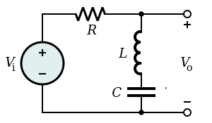
Band-stop filter can be represented as a combination of low-pass and high-pass filters.
Transfer function of the notch filter is presented below.

Here is zero circular frequency and is the pole circular frequency. Zero frequency is the cutoff frequency and sets the type of the notch filter: standard notch when , low-pass notch ( ) and high-pass notch ( ) filters. denotes the Q-factor[2].


For standard notch filter the formulation can be rewritten as

where is the central rejected frequency and is the width of the rejected band.


Examples
In the audio domain
- Anti-hum filter
For countries using 60 Hz power lines:
- Low Freq: 59 Hz
- Middle Freq 60 Hz
- High Freq: 61 Hz
This means that the filter passes all frequencies, except for the range of 59–61 Hz. This would be used to filter out the mains hum from the 60 Hz power line, though its higher harmonics could still be present.
For countries where power transmission is at 50 Hz, the filter would have a 49–51 Hz range.
In the radio frequency (RF) domain
- Non-linearities of power amplifiers
When measuring the non-linearities of power amplifiers, a very narrow notch filter can be very useful to avoid the carrier frequency. Use of the filter may ensure that the maximum input power of a spectrum analyser used to detect spurious content will not be exceeded.
- Wave trap
A notch filter, usually a simple LC circuit, is used to remove a specific interfering frequency. This is a technique used with radio receivers that are so close to a transmitter that it swamps all other signals. The wave trap is used to remove, or greatly reduce, the signal from the nearby transmitter.[3]
Optical Filtering (Wavelength Selection)
In optics, there are several methods of filtering selected wavelengths from a source or to a detector. Which rely on Scattering or destructive interference.
Filtering by Scattering and Diffraction
A Diffraction grating [4] or a Dispersive prism, may be used to selectively redirect selected wavelengths of light within an optical system.
In the case of transmission gratings and prisms, polychromatic light which passes through the object will be redirected according to wavelength. A slit may then be used to select wavelengths which are desired accordingly. A reflective grating may also be utilized via the same principle, though in this case light is reflected rather than transmitted. Filters by this design may either be: high pass/ band pass, or low pass; depending on system configuration.
Filtering by Interference
When using optics with real materials, light will be attenuated at various wavelengths through interference with the medium through which light traverses. In this sense, material selection may be utilized to selectively filter light according to the wavelengths which are minimally attenuated. To some extent, all real optical systems will suffer from this phenomena.
Alternatively, it is also possible to use an oscillating reflecting surface to cause destructive interference with reflected light along a single optical path. This principle is the basis for a Michelson Interferometer.
See also
- Parametric equalizer
- Bass instrument amplification (discusses use of notch filter to prevent feedback)
References
- ↑ "Band-stop filter", Federal Standard 1037C, accessed 14 May 2018
- ↑ "Chapter 8: Analog Filters". Basic Linear Design. USA: Analog Devices Inc. 2006.
- ↑ Carr, Joseph J. (2001). The technician's radio receiver handbook: Wireless and telecommunication technology, p. 282. Newnes. ISBN 0-7506-7319-2.
- ↑ Terracciano, Anthony (2018). "Hazardous Gas Detection Sensor Using Broadband Light-Emitting Diode-Based Absorption Spectroscopy for Space Applications". New Space. 6 (1): 28–36. doi:10.1089/space.2017.0044.