Norton's theorem
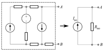
Known in Europe as the Mayer–Norton theorem, Norton's theorem holds, to illustrate in DC circuit theory terms (see that image):
- Any linear electrical network with voltage and current sources and only resistances can be replaced at terminals A–B by an equivalent current source Ino in parallel connection with an equivalent resistance Rno.
- This equivalent current Ino is the current obtained at terminals A-B of the network with terminals A-B short circuited.
- This equivalent resistance Rno is the resistance obtained at terminals A-B of the network with all its voltage sources short circuited and all its current sources open circuited.
For alternating current (AC) systems the theorem can be applied to reactive impedances as well as resistances.
The Norton equivalent circuit is used to represent any network of linear sources and impedances at a given frequency.
Norton's theorem and its dual, Thévenin's theorem, are widely used for circuit analysis simplification and to study circuit's initial-condition and steady-state response.
Norton's theorem was independently derived in 1926 by Siemens & Halske researcher Hans Ferdinand Mayer (1895–1980) and Bell Labs engineer Edward Lawry Norton (1898–1983).[1][2][3][4][5]
To find the equivalent,
- Find the Norton current Ino. Calculate the output current, IAB, with a short circuit as the load (meaning 0 resistance between A and B). This is Ino.
- Find the Norton resistance Rno. When there are no dependent sources (all current and voltage sources are independent), there are two methods of determining the Norton impedance Rno.
- Calculate the output voltage, VAB, when in open circuit condition (i.e., no load resistor – meaning infinite load resistance). Rno equals this VAB divided by Ino.
- or
- Replace independent voltage sources with short circuits and independent current sources with open circuits. The total resistance across the output port is the Norton impedance Rno.
This is equivalent to calculating the Thevenin resistance.
- However, when there are dependent sources, the more general method must be used. This method is not shown below in the diagrams.
- Connect a constant current source at the output terminals of the circuit with a value of 1 ampere and calculate the voltage at its terminals. This voltage divided by the 1 A current is the Norton impedance Rno. This method must be used if the circuit contains dependent sources, but it can be used in all cases even when there are no dependent sources.
Example of a Norton equivalent circuit
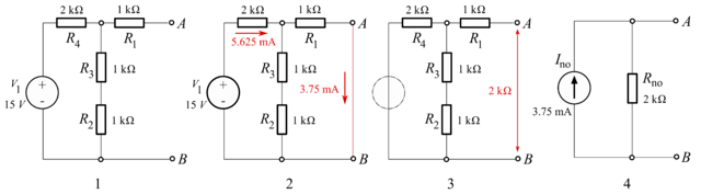
- The original circuit
- Calculating the equivalent output current
- Calculating the equivalent resistance
- Design the Norton equivalent circuit
In the example, the total current Itotal is given by:

The current through the load is then, using the current divider rule:


And the equivalent resistance looking back into the circuit is:

So the equivalent circuit is a 3.75 mA current source in parallel with a 2 kΩ resistor.
Conversion to a Thévenin equivalent
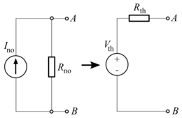
A Norton equivalent circuit is related to the Thévenin equivalent by the equations:


Queueing theory
The passive circuit equivalent of "Norton's theorem" in queuing theory is called the Chandy Herzog Woo theorem.[6][7] In a reversible queueing system, it is often possible to replace an uninteresting subset of queues by a single (FCFS or PS) queue with an appropriately chosen service rate.[8]
See also
References
Bibliography
- Brittain, J.E. (March 1990). "Thevenin's theorem". IEEE Spectrum. 27 (3): 42. doi:10.1109/6.48845. Retrieved 1 February 2013.
- Chandy, K. M.; Herzog, U.; Woo, L. (Jan 1975). "Parametric Analysis of Queuing Networks". IBM Journal of Research and Development. 19 (1): 36–42. doi:10.1147/rd.191.0036.
- Dorf, Richard C.; Svoboda, James A. (2010). "Chapter 5 – Circuit Theorems". Introduction to Electric Circuits (8th ed.). Hoboken, NJ: John Wiley & Sons. pp. 162–207. ISBN 978-0-470-52157-1.
- Gunther, N.J. (2004). Analyzing computer systems performance : with PERL::PDQ (Online-Ausg. ed.). Berlin: Springer. p. 281. ISBN 3-540-20865-8.
- Johnson, D.H. (2003). "Origins of the equivalent circuit concept: the voltage-source equivalent" (PDF). Proceedings of the IEEE. 91 (4): 636–640. doi:10.1109/JPROC.2003.811716.
- Johnson, D.H. (2003). "Origins of the equivalent circuit concept: the current-source equivalent" (PDF). Proceedings of the IEEE. 91 (5): 817–821. doi:10.1109/JPROC.2003.811795.
- Mayer, H. F. (1926). "Ueber das Ersatzschema der Verstärkerröhre (On equivalent circuits for electronic amplifiers]". Telegraphen- und Fernsprech-Technik. 15: 335–337.
- Norton, E. L. (1926). "Technical Report TM26–0–1860 – Design of finite networks for uniform frequency characteristic". Bell Laboratories.