Newton's rings

.jpeg)
Newton's rings is a phenomenon in which an interference pattern is created by the reflection of light between two surfaces—a spherical surface and an adjacent touching flat surface. It is named for Isaac Newton, who first studied the effect in 1717. When viewed with monochromatic light, Newton's rings appear as a series of concentric, alternating bright and dark rings centered at the point of contact between the two surfaces. When viewed with white light, it forms a concentric ring pattern of rainbow colors, because the different wavelengths of light interfere at different thicknesses of the air layer between the surfaces.
Phenomenon
The phenomenon was first described by Robert Hooke in his 1664 book Micrographia, although its name derives from the physicist Isaac Newton, who was the first to analyze it.
Theory
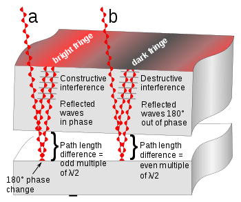

The pattern is created by placing a very slightly convex curved glass on an optical flat glass. The two pieces of glass make contact only at the center, at other points there is a slight air gap between the two surfaces, increasing with radial distance from the center. The diagram at right shows a small section of the two pieces, with the gap increasing right to left. Light from a monochromatic (single color) source shines through the top piece and reflects from both the bottom surface of the top piece and the top surface of the optical flat, and the two reflected rays combine and superpose. However the ray reflecting off the bottom surface travels a longer path. The additional path length is equal to twice the gap between the surfaces. In addition the ray reflecting off the bottom piece of glass undergoes a 180° phase reversal, while the internal reflection of the other ray from the underside of the top glass causes no phase reversal. The brightness of the reflected light depends on the difference in the path length of the two rays:
- Constructive interference (a): In areas where the path length difference between the two rays is equal to an odd multiple of half a wavelength (λ/2) of the light waves, the reflected waves will be in phase, so the "troughs" and "peaks" of the waves coincide. Therefore, the waves will reinforce (add) and the resulting reflected light intensity will be greater. As a result, a bright area will be observed there.
- Destructive interference (b): At other locations, where the path length difference is equal to an even multiple of a half-wavelength, the reflected waves will be 180° out of phase, so a "trough" of one wave coincides with a "peak" of the other wave. Therefore, the waves will cancel (subtract) and the resulting light intensity will be weaker or zero. As a result, a dark area will be observed there. Because of the 180° phase reversal due to reflection of the bottom ray, the center where the two pieces touch is dark.
This interference results in a pattern of bright and dark lines or bands called "interference fringes" being observed on the surface. These are similar to contour lines on maps, revealing differences in the thickness of the air gap. The gap between the surfaces is constant along a fringe. The path length difference between two adjacent bright or dark fringes is one wavelength λ of the light, so the difference in the gap between the surfaces is one-half wavelength. Since the wavelength of light is so small, this technique can measure very small departures from flatness. For example, the wavelength of red light is about 700 nm, so using red light the difference in height between two fringes is half that, or 350 nm, about 1/100 the diameter of a human hair. Since the gap between the glasses increases radially from the center, the interference fringes form concentric rings. For glass surfaces that are not spherical, the fringes will not be rings but will have other shapes.
For illumination from above, with a dark center, the radius of the Nth bright ring is given by
![{\displaystyle r_{N}=\left[\lambda R\left(N-{1 \over 2}\right)\right]^{1/2},}](../I/m/42e6b239fd5a47ddcdddcb24d6371338e82e2fc8.svg)
where N is the bright-ring number, R is the radius of curvature of the glass lens the light is passing through, and λ is the wavelength of the light.
The above formula is also applicable for dark rings for the ring pattern obtained by transmitted light.
Consider light incident on the flat plane of the convex lens that is situated on the optically flat glass surface below. The light passes through the glass lens until it comes to the glass-air boundary, where the transmitted light goes from a higher refractive index (n) value to a lower n value. The transmitted light passes through this boundary with no phase change. The reflected light (about 4% of the total) also has no phase change. The light that is transmitted into the air travels a distance, t, before it is reflected at the flat surface below; reflection at the air-glass boundary causes a half-cycle phase shift because the air has a lower refractive index than the glass. The reflected light at the lower surface returns a distance of (again) t and passes back into the lens. The two reflected rays will interfere according to the total phase change caused by the extra path length 2t and by the half-cycle phase change induced in reflection at the lower surface. When the distance 2t is less than a wavelength, the waves interfere destructively, hence the central region of the pattern is dark.
A similar analysis for illumination of the device from below instead of from above shows that in that case the central portion of the pattern is bright, not dark. (Compare the given example pictures to see this difference.)
Given the radial distance of a bright ring, r, and a radius of curvature of the lens, R, the air gap between the glass surfaces, t, is given to a good approximation by
- ,

where the effect of viewing the pattern at an angle oblique to the incident rays is ignored.
Thin-film interference
The phenomenon of Newton's rings is explained on the same basis as thin-film interference, including effects such as "rainbows" seen in thin films of oil on water or in soap bubbles. The difference is that here the "thin film" is a thin layer of air.
Further reading
- Airy, G.B. (1833). "VI.On the phænomena of Newton's rings when formed between two transparent substances of different refractive powers". Philosophical Magazine. Series 3. 2 (7): 20–30. doi:10.1080/14786443308647959. ISSN 1941-5966.
- Illueca, C.; Vazquez, C.; Hernandez, C.; Viqueira, V. (1998). "The use of Newton's rings for characterizing ophthalmic lenses". Ophthalmic and Physiological Optics. 18 (4): 360–371. doi:10.1046/j.1475-1313.1998.00366.x. ISSN 0275-5408.
- Dobroiu, Adrian; Alexandrescu, Adrian; Apostol, Dan; Nascov, Victor; Damian, Victor S. (2000). "Improved method for processing Newton's rings fringe patterns". 4068: 342–347. doi:10.1117/12.378693. ISSN 0277-786X.
- Tolansky, S. (2009). "XIV. New contributions to interferometry. Part II—New interference phenomena with Newton's rings". The London, Edinburgh, and Dublin Philosophical Magazine and Journal of Science. 35 (241): 120–136. doi:10.1080/14786444408521466. ISSN 1941-5982.
External links
| Wikimedia Commons has media related to Newton's rings. |
- Newton’s Ring from Eric Weisstein's World of Physics
- Photos
- Explanation of and expression for Newton's rings
- Newton's rings Video of a simple experiment with two lenses, and Newton's rings on mica observed. (On the website FizKapu.) (in Hungarian)