Machine (mechanical)
Machines employ power to achieve desired forces and movement (motion). A machine has a power source and actuators that generate forces and movement, and a system of mechanisms that shape the actuator input to achieve a specific application of output forces and movement. Modern machines often include computers and sensors that monitor performance and plan movement, and are called mechanical systems.
The meaning of the word "machine" is traced by the Oxford English Dictionary[1] to an independently functioning structure and by Merriam-Webster Dictionary[2] to something that has been constructed. This includes human design into the meaning of machine.
The adjective "mechanical" refers to skill in the practical application of an art or science, as well as relating to or caused by movement, physical forces, properties or agents such as is dealt with by mechanics.[1] Similarly Merriam-Webster Dictionary[3] defines "mechanical" as relating to machinery or tools.
Power flow through a machine provides a way to understand the performance of devices ranging from levers and gear trains to automobiles and robotic systems. The German mechanician Franz Reuleaux[4] wrote "a machine is a combination of resistant bodies so arranged that by their means the mechanical forces of nature can be compelled to do work accompanied by certain determinate motion." Notice that forces and motion combine to define power.
More recently, Uicker et al.[5] stated that a machine is "a device for applying power or changing its direction." And McCarthy and Soh[6] describe a machine as a system that "generally consists of a power source and a mechanism for the controlled use of this power."
Simple machines

The idea that a machine can be broken down into simple movable elements led Archimedes to define the lever, pulley and screw as simple machines. By the time of the Renaissance this list increased to include the wheel and axle, wedge and inclined plane.
Power sources
Natural forces such as wind and water powered larger mechanical systems. Waterwheels appeared around the world around 300 BC to use flowing water to generate rotary motion, which was applied to milling grain, and powering lumber, machining and textile operations. Modern water turbines use water flowing through a dam to drive an electric generator. Early windmills captured wind power to generate rotary motion for milling operations. Modern wind turbines also drives a generator. This electricity in turn is used to drive motors forming the actuators of mechanical systems.
The word engine derives from "ingenuity" and originally referred to contrivances that may or may not be physical devices. See Merriam-Webster's definition of engine. A steam engine uses heat to boil water contained in a pressure vessel; the expanding steam drives a piston or a turbine. This principle can be seen in the aeolipile of Hero of Alexandria. This is called an external combustion engine.
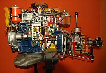
An automobile engine is called an internal combustion engine because it burns fuel (an exothermic chemical reaction) inside a cylinder and uses the expanding gases to drive a piston. A jet engine uses a turbine to compress air which is burned with fuel so that it expands through a nozzle to provide thrust to an aircraft, and so is also an "internal combustion engine."[8]
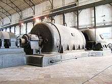
The heat from coal and natural gas combustion in a boiler generates steam that drives a steam turbine to rotate an electric generator. A nuclear power plant uses heat from a nuclear reactor to generate steam and electric power. This power is distributed through a network of transmission lines for industrial and individual use. Electric motors use either AC or DC electric current to generate rotational movement. Electric servomotors are the actuators for mechanical systems ranging from robotic systems to modern aircraft. Hydraulic and pneumatic systems use electrically driven pumps to drive water or air respectively into cylinders to power linear movement.
Mechanisms
A machine consists of an actuator input, a system of mechanisms that generate the output forces and movement, and an interface to the user. Electric motors, hydraulic and pneumatic actuators provide the input forces and movement. This input is shaped by mechanisms consisting of gears and gear trains, belt and chain drives, cam and follower mechanisms, and linkages as well as friction devices such as brakes and clutches. Structural components consist of the frame, fasteners, bearings, springs, lubricants and seals, as well as a variety of specialized machine elements such as splines, pins and keys.[4][5] The user interface ranges from switches and buttons to programmable logic controllers and includes the covers that provide texture, color and styling.
Gears and gear trains
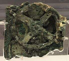
The transmission of rotation between contacting toothed wheels can be traced back to the Antikythera mechanism of Greece and the south-pointing chariot of China. Illustrations by the renaissance scientist Georgius Agricola show gear trains with cylindrical teeth. The implementation of the involute tooth yielded a standard gear design that provides a constant speed ratio. Some important features of gears and gear trains are:
- The ratio of the pitch circles of mating gears defines the speed ratio and the mechanical advantage of the gear set.
- A planetary gear train provides high gear reduction in a compact package.
- It is possible to design gear teeth for gears that are non-circular, yet still transmit torque smoothly.
- The speed ratios of chain and belt drives are computed in the same way as gear ratios. See bicycle gearing.
Cam and follower mechanisms
A cam and follower is formed by the direct contact of two specially shaped links. The driving link is called the cam (also see cam shaft) and the link that is driven through the direct contact of their surfaces is called the follower. The shape of the contacting surfaces of the cam and follower determines the movement of the mechanism.
Linkages
A linkage is a collection of links connected by joints. Generally, the links are the structural elements and the joints allow movement. Perhaps the single most useful example is the planar four-bar linkage. However, there are many more special linkages:
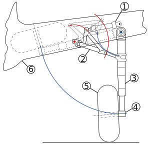
- Watt's linkage is a four-bar linkage that generates an approximate straight line. It was critical to the operation of his design for the steam engine. This linkage also appears in vehicle suspensions to prevent side-to-side movement of the body relative to the wheels. Also see the article Parallel motion.
- The success of Watt's linkage lead to the design of similar approximate straight-line linkages, such as Hoeken's linkage and Chebyshev's linkage.
- The Peaucellier linkage generates a true straight-line output from a rotary input.
- The Sarrus linkage is a spatial linkage that generates straight-line movement from a rotary input. Select this link for an animation of the Sarrus linkage
- The Klann linkage and the Jansen linkage are recent inventions that provide interesting walking movements. They are respectively a six-bar and an eight-bar linkage.
Planar mechanism
A planar mechanism is a mechanical system that is constrained so the trajectories of points in all the bodies of the system lie on planes parallel to a ground plane. The rotational axes of hinged joints that connect the bodies in the system are perpendicular to this ground plane.
Spherical mechanism
A spherical mechanism is a mechanical system in which the bodies move in a way that the trajectories of points in the system lie on concentric spheres. The rotational axes of hinged joints that connect the bodies in the system pass through the center of these circle.
Spatial mechanism
A spatial mechanism is a mechanical system that has at least one body that moves in a way that its point trajectories are general space curves. The rotational axes of hinged joints that connect the bodies in the system form lines in space that do not intersect and have distinct common normals.
Flexure mechanisms
A flexure mechanism consists of a series of rigid bodies connected by compliant elements (also known as flexure joints) that is designed to produce a geometrically well-defined motion upon application of a force.
Structural components
A number of machine elements provide important structural functions such as the frame, bearings, splines, spring and seals.
- The recognition that the frame of a mechanism is an important machine element changed the name three-bar linkage into four-bar linkage. Frames are generally assembled from truss or beam elements.
- Bearings are components designed to manage the interface between moving elements and are the source of friction in machines. In general, bearings are designed for pure rotation or straight line movement.
- Splines and keys are two ways to reliably mount an axle to a wheel, pulley or gear so that torque can be transferred through the connection.
- Springs provides forces that can either hold components of a machine in place or acts as a suspension to support part of a machine.
- Seals are used between mating parts of a machine to ensure fluids, such as water, hot gases, or lubricant do not leak between the mating surfaces.
- Fasteners such as screws, bolts, spring clips, and rivets are critical to the assembly of components of a machine. Fasteners are generally considered to be removable. In contrast, joining methods, such as welding, soldering, crimping and the application of adhesives, usually require cutting the parts to disassemble the components
Mechanics
Usher[9] reports that Hero of Alexandria's treatise on Mechanics focussed on the study of lifting heavy weights. Today mechanics refers to the mathematical analysis of the forces and movement of a mechanical system, and consists of the study of the kinematics and dynamics of these systems.
Dynamics of machines
The dynamic analysis of machines begins with a rigid-body model to determine reactions at the bearings, at which point the elasticity effects are included. The rigid-body dynamics studies the movement of systems of interconnected bodies under the action of external forces. The assumption that the bodies are rigid, which means that they do not deform under the action of applied forces, simplifies the analysis by reducing the parameters that describe the configuration of the system to the translation and rotation of reference frames attached to each body.[10][11]
The dynamics of a rigid body system is defined by its equations of motion, which are derived using either Newtons laws of motion or Lagrangian mechanics. The solution of these equations of motion defines how the configuration of the system of rigid bodies changes as a function of time. The formulation and solution of rigid body dynamics is an important tool in the computer simulation of mechanical systems.
Kinematics of machines
The dynamic analysis of a machine requires the determination of the movement, or kinematics, of its component parts, known as kinematic analysis. The assumption that the system is an assembly of rigid components allows rotational and translational movement to be modeled mathematically as Euclidean, or rigid, transformations. This allows the position, velocity and acceleration of all points in a component to be determined from these properties for a reference point, and the angular position, angular velocity and angular acceleration of the component.
Machine design
Machine design refers to the procedures and techniques used to address the three phases of a machine's lifecycle:
- invention, which involves the identification of a need, development of requirements, concept generation, prototype development, manufacturing, and verification testing;
- performance engineering involves enhancing manufacturing efficiency, reducing service and maintenance demands, adding features and improving effectiveness, and validation testing;
- recycle is the decommissioning and disposal phase and includes recovery and reuse of materials and components.
Machine elements
The elementary mechanical components of a machine are termed machine elements. These elements consist of three basic types (i) structural components such as frame members, bearings, axles, splines, fasteners, seals, and lubricants, (ii) mechanisms that control movement in various ways such as gear trains, belt or chain drives, linkages, cam and follower systems, including brakes and clutches, and (iii) control components such as buttons, switches, indicators, sensors, actuators and computer controllers.[12] While generally not considered to be a machine element, the shape, texture and color of covers are an important part of a machine that provide a styling and operational interface between the mechanical components of a machine and its users.
See also
References
- 1 2 Oxford English Dictionary
- ↑ Merriam-Webster Dictionary Definition of machine
- ↑ Merriam-Webster Dictionary Definition of mechanical
- 1 2 Reuleaux, F., 1876 The Kinematics of Machinery, (trans. and annotated by A. B. W. Kennedy), reprinted by Dover, New York (1963)
- 1 2 J. J. Uicker, G. R. Pennock, and J. E. Shigley, 2003, Theory of Machines and Mechanisms, Oxford University Press, New York.
- ↑ J. M. McCarthy and G. S. Soh, 2010, Geometric Design of Linkages, Springer, New York.
- ↑ Chambers, Ephraim (1728), "Table of Mechanicks", Cyclopaedia, A Useful Dictionary of Arts and Sciences, London, England, Volume 2, p. 528, Plate 11 .
- ↑ "Internal combustion engine", Concise Encyclopedia of Science and Technology, Third Edition, Sybil P. Parker, ed. McGraw-Hill, Inc., 1994, p. 998 .
- ↑ A. P. Usher, 1929, A History of Mechanical Inventions, Harvard University Press, (reprinted by Dover Publications 1968).
- ↑ B. Paul, Kinematics and Dynamics of Planar Machinery, Prentice-Hall, NJ, 1979
- ↑ L. W. Tsai, Robot Analysis: The mechanics of serial and parallel manipulators, John-Wiley, NY, 1999.
- ↑ Robert L. Norton, Machine Design, (4th Edition), Prentice-Hall, 2010
Further reading
- Oberg, Erik; Franklin D. Jones; Holbrook L. Horton; Henry H. Ryffel (2000). Christopher J. McCauley; Riccardo Heald; Muhammed Iqbal Hussain, eds. Machinery's Handbook (26th ed.). New York: Industrial Press Inc. ISBN 0-8311-2635-3.
- Reuleaux, Franz (1876). The Kinematics of Machinery. Translated by A. B. W. Kennedy. New York: reprinted by Dover (1963).
- Uicker, J. J.; G. R. Pennock; J. E. Shigley (2003). Theory of Machines and Mechanisms. New York: Oxford University Press.