Ring counter
A ring counter is a type of counter composed of flip-flops connected into a shift register, with the output of the last flip-flop fed to the input of the first, making a "circular" or "ring" structure.
There are two types of ring counters:
- A straight ring counter, also known as a one-hot counter, connects the output of the last shift register to the first shift register input and circulates a single one (or zero) bit around the ring.
- A twisted ring counter, also called switch-tail ring counter, walking ring counter, Johnson counter, or Möbius counter, connects the complement of the output of the last shift register to the input of the first register and circulates a stream of ones followed by zeros around the ring.
Four-bit ring-counter sequences
| Straight ring counter | Johnson counter | |||||||||
|---|---|---|---|---|---|---|---|---|---|---|
| State | Q0 | Q1 | Q2 | Q3 | State | Q0 | Q1 | Q2 | Q3 | |
| 0 | 1 | 0 | 0 | 0 | 0 | 0 | 0 | 0 | 0 | |
| 1 | 0 | 1 | 0 | 0 | 1 | 1 | 0 | 0 | 0 | |
| 2 | 0 | 0 | 1 | 0 | 2 | 1 | 1 | 0 | 0 | |
| 3 | 0 | 0 | 0 | 1 | 3 | 1 | 1 | 1 | 0 | |
| 0 | 1 | 0 | 0 | 0 | 4 | 1 | 1 | 1 | 1 | |
| 1 | 0 | 1 | 0 | 0 | 5 | 0 | 1 | 1 | 1 | |
| 2 | 0 | 0 | 1 | 0 | 6 | 0 | 0 | 1 | 1 | |
| 3 | 0 | 0 | 0 | 1 | 7 | 0 | 0 | 0 | 1 | |
| 0 | 1 | 0 | 0 | 0 | 0 | 0 | 0 | 0 | 0 | |
Properties
Ring counters are often used in hardware design (e.g. ASIC and FPGA design) to create finite-state machines. A binary counter would require an adder circuit which is substantially more complex than a ring counter and has higher propagation delay as the number of bits increases, whereas the propagation delay of a ring counter will be nearly constant regardless of the number of bits in the code.
The straight and twisted forms have different properties, and relative advantages and disadvanteages.
A general disadvantage of ring counters is that they are lower density codes than normal binary encodings of state numbers. A binary counter can represent 2^N states, where N is the number of bits in the code, whereas a straight ring counter can represent only N states and a Johnson counter can represent only 2N states. This may be an important consideration in hardware implementations where registers are more expensive than combinational logic.
Johnson counters are sometimes favored, because they offer twice as many count states from the same number of shift registers, and because they are able to self-initialize from the all-zeros state, without requiring the first count bit to be injected externally at start-up. The Johnson counter generates a code in which adjacent states differ by only one bit (that is, have a Hamming distance of 1), as in a Gray code, which can be useful if the bit pattern is going to be asynchronously sampled.[1]
When a fully decoded or one-hot representation of the counter state is needed, as in some sequence controllers, the straight ring counter is preferred. The one-hot property means that the set of codes are separated by a minimum Hamming distance of 2,[2] so any single-bit error is detectable (as is any error pattern other than turning on one bit and turning off one bit).
Sometimes bidirectional shift registers are used (using multiplexors to take the input for each flip-flop from its left or right neighbor), so that bidirectional or up–down ring counters can be made.[3]
Logic diagrams
The straight ring counter has the logical structure shown here:
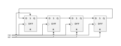
Instead of the reset line setting up the initial one-hot pattern, the straight ring is sometimes made self-initializing by the use of a distributed feedback gate across all of the outputs except that last, so that a 1 in presented at the input when there is no 1 in any stage but the last.[4]
A Johnson counter, named for Robert Royce Johnson, is a ring with an inversion; here is a 4-bit Johnson counter:
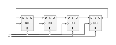
Note the small bubble indicating inversion of the Q signal from the last shift register before feeding back to the first D input, making this a Johnson counter.
History
Before the days of digital computing, digital counters were used to measure rates of random events such as radioactive decays to alpha and beta particle. Fast "pre-scaling" counters reduced the rate of random events to more manageable and more regular rates. Five-state ring counters were used along with divide-by-two scalers to make decade (power-of-ten) scalers before 1940, such as those developed by C. E. Wynn-Williams.[5]
Early ring counters used only one active element (vacuum tube, valve, or transistor) per stage, relying on global feedback rather than local bistable flip-flops, to suppress states other than the one-hot states, for example in the 1941 patent filing of Robert E. Mumma of the National Cash Registor Company.[6] Wilcox P. Overbeck invented a version using multiple anodes in a single vacuum tube,[7][8] In recognition of his work, ring counters are sometimes referred to as "Overbeck rings"[9][10] (and after 2006, sometimes as "Overbeck counters", since Wikipedia used that term from 2006 to 2018).
The ENIAC used decimal arithmetic based on 10-state one-hot ring counters. The works of Mumma at NCR and Overbeck at MIT were among the prior art works examined by the patent office in invalidated the patents of J. Presper Eckert and John Mauchly for the ENIAC technology.[11]
By the 1950s, ring counters with a two-tube or twin-triode flip-flop per stage were appearing.[12]
Robert Royce Johnson developed a number of different shift-register-based counters with the aim of making different numbers of states with the simplest possible feedback logic, and filed for a patent in 1953.[13] The Johnson counter is the simplest of these.
Applications
Early applications of ring counters were as frequency prescalers (e.g. for Geiger counter and such instruments),[5] and for counting pattern occurrences in cryptanalysis (e.g. in the Heath Robinson codebreaking machine and the Colossus computer),[14] and for decimal arithmetic in computers and calculators, either as bi-quinary (as in the Colossus) or as ten-state one-hot representations (as in the ENIAC).
Straight ring counters generate fully decoded one-hot codes to that are often used to enable a specific action in each state of a cyclic control cycle. One-hot codes can also be decoded from a Johnson counter, using one gate for each state.[15]
Besides being an efficient alternative way to generate one-hot codes and frequency pre-scalers, a Johnson counters is also a simple way to encode a cycle of states that can be asynchronously sampled without glitching, since only one bit changes at a time, as in a Gray code. Early computer mice used up–down (bidirectional) 2-bit Johnson or Gray encodings to indicate motion in each dimensions, though they were not necessarily generated by rings of flip-flops.[16]
See also
References
- ↑ Pedroni, Volnei A. (2013). Finite State Machines in Hardware: Theory and Design. MIT Press. p. 50. ISBN 9780262019668.
- ↑ Mengibar, Luis, Luis Entrena, Michael G. Lorenz, and Raúl Sánchez-Reillo (2003). "State Encoding for Low-Power FSMs in FPGA". Integrated Circuit and System Design. Power and Timing Modeling, Optimization and Simulation: 13th International Workshop, PATMOS 2003, Torino, Italy, September 10-12, 2003, Proceedings, Volume 13. Springer Science & Business Media. p. 35.
- ↑ Stan, Mircea R (1997). "Synchronous up/down counter with clock period independent of counter size" (PDF). Proceedings 13th IEEE Symposium on Computer Arithmetic: 274–281.
- ↑ Brian Holdsworth and Clive Woods (2002). Digital Logic Design. pp. 191–192. ISBN 9780080477305.
- 1 2 Lewis, W. B. (1942). Electrical Counting: With Special Reference to Counting Alpha and Beta Particles. Cambridge University Press. p. 90.
- ↑ "Electronic accumulation", Robert E. Mumma's US Patent No. 2405096, filed in 1941
- ↑ "Electronic switching device", Wilcox P. Overbeck's US Patent No. 2427533, filed in 1943
- ↑ Dayton Codebreakers: 1942 Research Report, mentioning "A new high speed counter by Mr. Overbeck, January 8, 1942"
- ↑ "RAMAC 305", IBM Customer Engineering Manual of Instruction (1959), "The Overbeck ring is used to supply timed pulses within computer circuits much as cam operated circuit breakers supply timed pulses on mechanical machines. It consists of a set of triggers with a common input from the ring drive line which carries pulses supplied by the process drum. ... Initially the triggers are reset OFF with the exception of the home trigger, which is ON. Each negative input pulse will turn OFF the trigger that is ON. The fall of the voltage at pin 10 of the trigger being turned OFF will grid flip the next trigger ON. This continues through a closed ring..."
- ↑ Technical Education Program Series, United States. Division of Vocational and Technical Education, 1960, p. 52
- ↑ B. Randall (2014). "The Origins of Digital Computers: Supplementary Bibliography". In Nicholas Metropolis. History of Computing in the Twentieth Century. Elsevier. pp. 651–652.
- ↑ William A Higinbotham , "Fast impulse circuits", US Patent No. 2536808
- ↑ Robert R. Johnson, "Electronic counter", US Patent No. 3030581
- ↑ Copeland, B. Jack (2010). Colossus: The Secrets of Bletchley Park's Code-breaking Computers. Oxford University Press. pp. 123–128. ISBN 9780199578146.
- ↑ Gideon Langholz, Abraham Kandel, and Joe L. Mott (1998). Foundations of Digital Logic Design. World Scientific. pp. 525–526. ISBN 9789810231101.
- ↑ Richard F. Lyon (1981), "The Optical Mouse, and an Architectural Methodology for Smart Digital Sensors", Xerox PARC report. "The counters needed for X and Y simply count through four states, in either direction (up or down), changing only one bit at a time (i.e., 00, 01, 11, 10). This is a simple case of either a Gray-code counter or a Johnson counter (Moebius counter)."