Passive integrator circuit
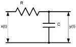
Passive integrator circuit is a simple four-terminal network consisting of two passive elements. It is also the simplest (first-order) low-pass filter.
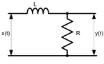
We'll analyze only the first circuit; the second is very similar.
Transfer function
A transfer ratio is a gain factor for the sinusoidal input signal with given frequency.
A transfer function shows the dependence of the transfer ratio from the signal frequency, given that the input signal is sinusoidal.
According to Ohm's law,

where and are input and output signals' amplitudes respectively, and and are the resistor's and capacitor's impedances.


Therefore, the complex transfer function is

where

Amplitude transfer function

Phase transfer function

Transfer functions for the second circuit are the same (with ).

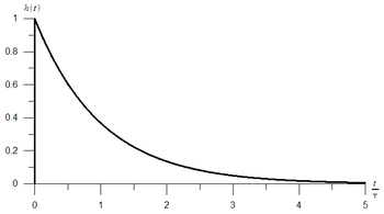
Impulse response
The circuit's Impulse response can be derived as an inverse Laplace transform of the complex transfer function:

where is a time constant.

Applications
A passive integrator circuit can serve as a simple integrator. It is also one of the basic electronic circuits, being widely used in circuit analysis based on the equivalent circuit method.
It is often used in cheap digital audio systems (i.e. cheap soundcards) as a reconstruction filter.