Connectors for car audio
Several types of connectors for car audio systems are used.
Splicing wires
Splicing wires used in car audio are mainly for power, ground, amplifier and antenna, speakers, phone and others.
Power and ground
- ACC (red), supplies +12V power to car audio and other accessories, only when the car is ignited.
- Constant (yellow), also called BAT or Battery, provides permanent +12V power from battery.
- Illumination (orange with white stripe) or dimmer, when it is night and cars lights are turned on, head unit screen illumination is dimmed.
- Ground, abbrev. as GND (black), 0V, usually connected to the vehicle's metal chassis and body.
Speakers
Wires with black stripe are for negative power:
- Right front speaker: gray.
- Left front speaker: white.
- Right rear: purple.
- Left rear: green.
Amplifier and Antenna
They have low amperage and it is activated when radio is turned on.
- Antenna: blue.
- Amplifier remote turn on: blue with white stripe.
Phone And Others
- Phone : the cable to mute when receiving a call, is brown.
- Back view, orange with white strip, works when reverse gear light is on and it is used to turn on back camera screen (i.e. when parking).
- Steering Wheel Controls, SWC or Key, brown with black stripe, usually employs CAN bus.
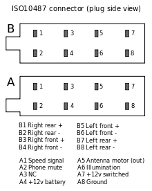
ISO 10487 Harness Adapter

ISO 10487 defines a standard for connectors for the head unit to the car's electrical system, consisting of a system of four different connectors typically used in head units for car audio.
Parts
Part 1 of the standard is dedicated to "Dimensions and general requirements" and Part 2 to "Performance requirements".
Power (A)
The first connector A is always present, is usually black in colour, and contains pins for power-supply, off/on (typically controlled by ignition key), optional control for a motorised antenna and so on.
- On some cars the +12V Ignition and Battery positions are reversed, such as later Volkswagen Group cars, Peugeot 106, Vauxhall Astra, Citroën C3 and some JCB tractors.
- Pin 1 is optional; used for speed dependent volume control and possibly navigation.
- Pin 2 is optional; used for phone mute
- Pin 3 is optional; used for reversing lamp signal on Becker radios with navigation.
- Pin 6 is optional; used for vehicle instrument illumination
Loudspeaker (B)
The second connector B is for connecting four loudspeakers, front, rear, left and right, and is usually brown in colour.
Miscellaneous (C)
The connector C is optional. Some times, it appears as one 20-pin connector, often red in colour, or it may be divided into three separate connectors which may be hooked together, in which case C1 is usually yellow, C2 is usually green which C3 is usually blue in colour. The contact spacing is narrower than the other connectors, so the C connector is sometimes referred to as mini-ISO.
| 1) line out left rear | 4) line out left front | |||
| 3) line out common ground | 6) +12V switched (out) | |||
| 2) line out right rear | 5) line out right front | |||
| 7) receive data | 10) +12V switched (out) | |||
| 9) chassis ground | 12) remote control ground | |||
| 8) transmit data | 11) remote control in | |||
| 13) data in (bus) | 16) +12v switched (out) | 19) audio left | |||
| 15) +12v permanent (out) | 18) audio ground | ||||
| 14) data out | 17) data ground | 20) audio right | |||
Note: ISO 10487 only defines the physical attributes of the connectors, not the pin/signal designations, which are manufacturer-defined. The example above is oriented towards VW vehicles only.
Navigation (D)
The connector D is for satellite navigation systems. It has 10 pins.
Quadlock
From 2000 and onwards, manufacturers, such as BMW, Citroen, Ford, Mercedes Benz, Peugeot, Volkswagen, Rover, Audi, Seat, Opel and Škoda have sometimes started using a 40 pin connector instead, called the Quadlock. The Quadlock connector consists of a block of 16 flat pins analogous to the two main ISO 10487 connectors. While the physical contact pins are the same, the pin allocation is not entirely the same, and the connector housing is not compatible. In addition to the 16 pins, like ISO 10487, there are minor connectors for optional equipment. They fit within the frame of the main connector, and has coding so that they cannot be interchanged. Minor connector B has 12 pins for audio output signals. Minor connector C has 12 pins for various audio sources such as CD-changers, MP3 players.
| 1) right rear + | 5) right rear - | 9) I-bus (BMW) / Canbus+ | 13) antenna (out) | |
| 2) right front + | 6) right front - | 10) phone mute / (Speed Signal) | 14) illumination | |
| 3) left front + | 7) left front - | 11) tel on / Canbus- | 15) 12V battery | |
| 4) left rear + | 8) left rear - | 12) ground | 16) 12V switched | |
See also
- CAN bus
- Car antenna jack
- Car radio
- Dashboard
- Dashcam
- Fuse (automotive)
- ISO 7736, standard for car radio enclosures
- Car
- Universal steering wheel control interface
External links
- Quadlock connector with physical measurements.
- Car Audio ISO connector pinout.
- ISO 10487 Passenger car radio connections
- Part 1: Dimensions and general requirements
- Part 2: Performance requirements