Hart's inversor

Hart's (first) inversor. Links of the same color are the same length. The relative position of the fixed point, the input, and the output along their links is the same (half, here).
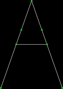
Hart's A-frame, or Hart's second inversor. The short links are half the length of the long ones. The center link is one quarter of the way down the long links. A fixed link along the bottom of the same length as the long links is not shown.
Hart's inversor is one of two mechanisms that provides a perfect straight line motion without sliding guides.[1]
They were invented and published by Harry Hart in 1874–5.[1][2]
Hart's first inversor is based on an antiparallelogram. The addition of fixed points and a driving arm make it a 6-bar linkage.
It can be used to convert rotary motion to a perfect straight line by fixing a point on one short link and driving a point on another link in a circular arc.[1][3]
Hart's second inversor, also known as "Hart's A-frame", is less flexible in its dimensions, but has the useful property that the motion perpendicularly bisects the fixed base points.
Example dimensions
 dimensions:
AB = 4
AC = BD = 4
CE = ED = 2
Af = Bg = 3
fC = gD = 1
fg = 2.png) dimensions:
dimensions:
AB = Bg = 2
AC = AE = 3
CD = EF = 12
EC = FD = 6
Cp = pD = 6
Eg = 6
See also
- Straight line mechanism
- Four-bar linkage
- Quadruplane inversor a generalization of Hart's first inversor
References
External links
| Wikimedia Commons has media related to Hart's inversor. |
- bham.ac.uk – Hart's A-frame (draggable animation) 6-bar linkage
This article is issued from
Wikipedia.
The text is licensed under Creative Commons - Attribution - Sharealike.
Additional terms may apply for the media files.