Fluidized bed
A fluidised bed is a physical phenomenon occurring when a quantity of a solid particulate substance (usually present in a holding vessel) is placed under appropriate conditions to cause a solid/fluid mixture to behave as a fluid. This is usually achieved by the introduction of pressurized fluid through the particulate medium. This results in the medium then having many properties and characteristics of normal fluids, such as the ability to free-flow under gravity, or to be pumped using fluid type technologies.
The resulting phenomenon is called fluidisation. Fluidised beds are used for several purposes, such as fluidized bed reactors (types of chemical reactors), solids separation[1], fluid catalytic cracking, fluidized bed combustion, heat or mass transfer or interface modification, such as applying a coating onto solid items. This technique is also becoming more common in aquaculture for the production of shellfish in integrated multi-trophic aquaculture systems.[2]
Properties
A fluidised bed consists of fluid-solid mixture that exhibits fluid-like properties. As such, the upper surface of the bed is relatively horizontal, which is analogous to hydrostatic behavior. The bed can be considered to be a heterogeneous mixture of fluid and solid that can be represented by a single bulk density.
Furthermore, an object with a higher density than the bed will sink, whereas an object with a lower density than the bed will float, thus the bed can be considered to exhibit the fluid behavior expected of Archimedes' principle. As the "density", (actually the solid volume fraction of the suspension), of the bed can be altered by changing the fluid fraction, objects with different densities comparative to the bed can, by altering either the fluid or solid fraction, be caused to sink or float.
In fluidised beds, the contact of the solid particles with the fluidisation medium (a gas or a liquid) is greatly enhanced when compared to packed beds. This behavior in fluidised combustion beds enables good thermal transport inside the system and good heat transfer between the bed and its container. Similarly to the good heat transfer, which enables thermal uniformity analogous to that of a well mixed gas, the bed can have a significant heat-capacity whilst maintaining a homogeneous temperature field.
Application
Fluidised beds are used as a technical process which has the ability to promote high levels of contact between gases and solids. In a fluidised bed a characteristic set of basic properties can be utilised, indispensable to modern process and chemical engineering, these properties include:
- Extremely high surface area contact between fluid and solid per unit bed volume
- High relative velocities between the fluid and the dispersed solid phase.
- High levels of intermixing of the particulate phase.
- Frequent particle-particle and particle-wall collisions.
Taking an example from the food processing industry: fluidised beds are used to accelerate freezing in some individually quick frozen (IQF) tunnel freezers. These fluidised bed tunnels are typically used on small food products like peas, shrimp or sliced vegetables, and may use cryogenic or vapor-compression refrigeration. The fluid used in fluidised beds may also contain a fluid of catalytic type; that's why it is also used to catalyse the chemical reaction and also to improve the rate of reaction.
Fluidised beds are also used for efficient bulk drying of materials. Fluidised bed technology in dryers increases efficiency by allowing for the entire surface of the drying material to be suspended and therefore exposed to the air. This process can also be combined with heating or cooling, if necessary, according to the specifications of the application.
History
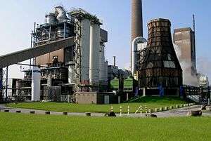
In 1922, Fritz Winkler made the first industrial application of fluidisation in a reactor for a coal gasification process.[3] In 1942, the first circulating fluid bed was built for catalytic cracking of mineral oils, with fluidisation technology applied to metallurgical processing (roasting arsenopyrite) in the late 1940s.[4][5] During this time theoretical and experimental research improved the design of the fluidised bed. In the 1960s VAW-Lippewerk in Lünen, Germany implemented the first industrial bed for the combustion of coal and later for the calcination of aluminium hydroxide.
Fluidised bed types
Bed types can be coarsely classified by their flow behavior, including:[6]
- Stationary or bubbling fluidised bed is the classical approach where the gas at low velocities is used and fluidisation of the solids is relatively stationary, with some fine particles being entrained.
- Circulating fluidized beds (CFB), where gases are at a higher velocity sufficient to suspend the particle bed, due to a larger kinetic energy of the fluid. As such the surface of the bed is less smooth and larger particles can be entrained from the bed than for stationary beds. Entrained particles are recirculated via an external loop back into the reactor bed. Depending on the process, the particles may be classified by a cyclone separator and separated from or returned to the bed, based upon particle cut size.
- Vibratory fluidized beds are similar to stationary beds, but add a mechanical vibration to further excite the particles for increased entrainment.
- Transport or flash reactor (FR). At velocities higher than CFB, particles approach the velocity of the gas. Slip velocity between gas and solid is significantly reduced at the cost of less homogeneous heat distribution.
- Annular fluidized bed (AFB). A large nozzle at the center of a bubble bed introduces gas as high velocity achieving the rapid mixing zone above the surrounding bed comparable to that found in the external loop of a CFB.
- Mechanically Fluidised Reactor (MFR). A mechanical stirrer is used to mobilize particles and achieve properties similar to that a well-mixed fluidised bed. It does not require fluidisation gas.[7]
Bed design
Basic model
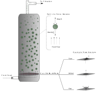
When the packed bed has a fluid passed over it, the pressure drop of the fluid is approximately proportional to the fluid's superficial velocity. In order to transition from a packed bed to a fluidised condition, the gas velocity is continually raised. For a free-standing bed there will exist a point, known as the minimum or incipient fluidisation point, whereby the bed's mass is suspended directly by the flow of the fluid stream. The corresponding fluid velocity, known as the "minimum fluidisation velocity", .[8]

Beyond the minimum fluidisation velocity ( ), the bed material will be suspended by the gas-stream and further increases in the velocity will have a reduced effect on the pressure, owing to sufficient percolation of the gas flow. Thus the pressure drop for is relatively constant.


At the base of the vessel the apparent pressure drop multiplied by the cross-section area of the bed can be equated to the force of the weight of the solid particles (less the buoyancy of the solid in the fluid).
![\Delta p_{w}=H_{w}(1-\epsilon _{w})(\rho _{s}-\rho _{f})g=[M_{s}g/A][(\rho _{s}-\rho _{f})/\rho _{s}]](../I/m/39abadfa7170965822feee6e7e66f86664ae9e47.svg)
where:
is the bed pressure drop

is the bed height

is the bed voidage, i.e. the fraction of the bed volume that is occupied by the voids (the fluid spaces between the particles)

is the apparent density of bed particles

is the density of the fluidising fluid

is the gravity acceleration

is the total mass of solids in the bed

is the cross-sectional area of the bed

Geldart Groupings
In 1973, Professor D. Geldart proposed the grouping of powders in to four so-called "Geldart Groups".[9] The groups are defined by their locations on a diagram of solid-fluid density difference and particle size. Design methods for fluidised beds can be tailored based upon the particle's Geldart grouping:[8]
Group A For this group the particle size is between 20 and 100 µm, and the particle density is typically less than 1.4g/cm3. Prior to the initiation of a bubbling bed phase, beds from these particles will expand by a factor of 2 to 3 at incipient fluidisation, due to a decreased bulk density. Most powder-catalyzed beds utilize this group.
Group B The particle size lies between 40 and 500 µm and the particle density between 1.4-4g/cm3. Bubbling typically forms directly at incipient fluidisation.
Group C This group contains extremely fine and consequently the most cohesive particles. With a size of 20 to 30 µm, these particles fluidise under very difficult to achieve conditions, and may require the application of an external force, such as mechanical agitation.
Group D The particles in this region are above 600 µm and typically have high particle densities. Fluidisation of this group requires very high fluid energies and is typically associated with high levels of abrasion. Drying grains and peas, roasting coffee beans, gasifying coals, and some roasting metal ores are such solids, and they are usually processed in shallow beds or in the spouting mode.
Distributor
Typically, pressurized gas or liquid enters the fluidised bed vessel through numerous holes via a plate known as a distributor plate, located at the bottom of the fluidised bed. The fluid flows upward through the bed, causing the solid particles to be suspended. If the inlet fluid is disabled, the bed may settle, pack onto the plate or trickle down through the plate. Many industrial beds use a sparger distributor instead of a distributor plate. The fluid is then distributed through a series of perforated tubes.
See also
- Cyclonic separation - A method of separating gases and particulate matter
- Fluidisation - Principles and theory of fluidisation
- Fluidized bed combustion - Application of fluidised beds to combustion
- Fluidized bed reactor - Application of fluidised beds to reactive chemical processes
- Fluidized bed concentrator - Application of fluidised beds to remove VOCs/HAPs from industrial exhaust
- Unit operation - Other Engineering unit operations
- Chemical looping combustion - Dual fluidised bed application
References
- ↑ Peng, Z.; Moghtaderi, B.; Doroodchi, E. (2017), A simple model for predicting solid concentration distribution in binary‐solid liquid fluidized beds, AIChE Journal, p. 469:484, doi:10.1002/aic.15420
- ↑ Wang, JK, 2003. Conceptual design of a microalgae-based recirculating oyster and shrimp system. Aquacultural Engineering 28, 37-46
- ↑ Grace, John R.; Leckner, Bo; Zhu, Jesse; Cheng, Yi (2008), "Fluidised Beds", in Clayton T. Crow, Multiphase Flow Handbook, CRC Press, p. 5:71, doi:10.1201/9781420040470.ch5, ISBN 978-1-4200-4047-0, retrieved June 2012 Check date values in:
|accessdate=(help) - ↑ Office of Communications (November 3, 1998), The Fluid Bed Reactor:Baton Rouge, Louisiana (pdf), American Chemical Society, retrieved June 2012 Check date values in:
|accessdate=(help) - ↑ Grace; Leckner; Zhu; Cheng, p. 5:75 Missing or empty
|title=(help) - ↑ Fluidisation technology, Outotec, May 2007, retrieved June 2012 Check date values in:
|accessdate=(help) - ↑ Chaudhari, Mitesh C., "Effect of Liquid-Solid Contact on Thermal Cracking of Heavy Hydrocarbons in a Mechanically Fluidised Reactor" (2012). Electronic Thesis and Dissertation Repository. Paper 1009. http://ir.lib.uwo.ca/etd/1009
- 1 2 Holdich, Richard Graham (November 1, 2002), "Chapter 7: Fluidisation", Fundamentals of Particle Technology (pdf), Midland Information Technology & Publishing, ISBN 978-0954388102, retrieved June 2012 Check date values in:
|accessdate=(help) - ↑ Geldart, D. (1973). "Types of gas fluidisation". Powder technology. 7 (5): 285–292. doi:10.1016/0032-5910(73)80037-3.