Eye pattern
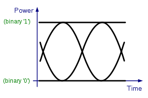
In telecommunication, an eye pattern, also known as an eye diagram, is an oscilloscope display in which a digital signal from a receiver is repetitively sampled and applied to the vertical input, while the data rate is used to trigger the horizontal sweep. It is so called because, for several types of coding, the pattern looks like a series of eyes between a pair of rails. It is a tool for the evaluation of the combined effects of channel noise and intersymbol interference on the performance of a baseband pulse-transmission system. It is the synchronised superposition of all possible realisations of the signal of interest viewed within a particular signaling interval.
Several system performance measures can be derived by analyzing the display. If the signals are too long, too short, poorly synchronized with the system clock, too high, too low, too noisy, or too slow to change, or have too much undershoot or overshoot, this can be observed from the eye diagram. An open eye pattern corresponds to minimal signal distortion. Distortion of the signal waveform due to intersymbol interference and noise appears as closure of the eye pattern.[1][2][3]
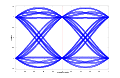
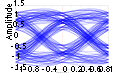
Example
Measurements
There are many measurements that can be obtained from an eye diagram:[4]
Amplitude measurements
- Eye amplitude
- Eye crossing amplitude
- Eye crossing percentage
- Eye height
- Eye level
- Eye signal-to-noise ratio
- Quality factor
- Vertical eye opening
Time measurements
- Deterministic jitter
- Eye crossing time
- Eye delay
- Eye fall time
- Eye rise time
- Eye width
- Horizontal eye opening
- Peak-to-peak jitter
- Random jitter
- RMS jitter
- CRC jitter
- Total jitter
Interpreting measurements
| Eye-diagram feature | What it measures |
|---|---|
| Eye opening (height, peak to peak) | Additive noise in the signal |
| Eye overshoot/undershoot | Peak distortion due to interruptions in the signal path |
| Eye width | Timing synchronization & jitter effects |
| Eye closure | Intersymbol interference, additive noise |
See also
Notes
- ↑ Christopher M. Miller "High-Speed Digital Transmitter Characterization Using Eye Diagram Analysis". 1266 Hewlett-Packard Journal 45(1994) Aug., No,4, pp. 29-37.
- ↑

- ↑ John G Proakis, Digital Communications 3rd ed, 2001
- ↑ "Matlab's help file description of how to use the Eye Diagram Functions in the Communications Toolbox".
References
External links
| Wikimedia Commons has media related to Eye diagrams. |
- Ruckerbauer, Hermann. "An Eye is Born". Gives an example video of construction of an eye pattern
- Understanding Data Eye Diagram Methodology for Analyzing High Speed Digital Signals