Electronic color code
An electronic color code is used to indicate the values or ratings of electronic components, usually for resistors, but also for capacitors, inductors, diodes and others. A separate code, the 25-pair color code, is used to identify wires in some telecommunications cables. Different codes are used for wire leads on devices such as transformers or in building wiring.
History
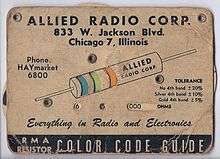
The electronic color code was developed in the early 1920s by the Radio Manufacturers Association (RMA), later the Radio Electronics Television Manufacturers' Association (RETMA), now part of the Electronic Industries Alliance (EIA)[1] Therefore, the code was known as RMA, RTMA, RETMA or EIA color code. In 1952, it was standardized in IEC 62:1952 by the International Electrotechnical Commission (IEC) and since 1963 also published as EIA RS-279.[2] Originally only meant to be used for fixed resistors, the color code was extended to also cover capacitors with IEC 62:1968. The code was adopted by many national standards like DIN 40825 (1973), BS 1852 (1974) and IS 8186 (1976). The current international standard defining marking codes for resistors and capacitors is IEC 60062:2016[3] and EN 60062:2016. In addition to the color code, these standards define a letter and digit code for resistors and capacitors.
Color bands were used because they were easily and cheaply printed on tiny components. However, there were drawbacks, especially for color blind people. Overheating of a component or dirt accumulation may make it impossible to distinguish brown from red or orange. Advances in printing technology have now made printed numbers more practical on small components. The values of components in surface mount packages are marked with printed alphanumeric codes instead of a color code.
Resistor color-coding
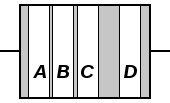
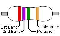
To distinguish left from right there is a gap between the C and D bands.
- The first significant figure of component value (left side)
- The second significant figure (some precision resistors have a third significant figure, and thus five bands).
- The decimal multiplier (number of trailing zeroes)
- If present, indicates tolerance of value in percent (no band means 20%)
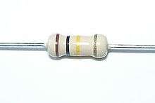
In the above example, a resistor with bands of red, violet, green, and brown has first digit 2 (red; see table below), second digit 7 (violet), followed by 5 (green) zeroes: 2700000 ohms. Gold signifies that the tolerance is ±5%.
Resistors manufactured for military use may also include a fifth band which indicates component failure rate (reliability); refer to MIL-HDBK-199[4] for further details.
Tight tolerance resistors may have three bands for significant figures rather than two, or an additional band indicating temperature coefficient, in units of ppm/K.
All coded components have at least two value bands and a multiplier; other bands are optional.
The standard color code per IEC 60062:2016 is as follows:
| Ring color | Significant figures | Multiplier | Tolerance | Temperature coefficient | |||||
|---|---|---|---|---|---|---|---|---|---|
| Name | Code | RAL | Percent [%] | Letter | [ppm/K] | Letter | |||
| None | – | – | – | – | ±20 | M | – | ||
| Pink | PK | 3015 | – | ×10−3[3] | ×0.001 | – | – | ||
| Silver | SR | – | – | ×10−2 | ×0.01 | ±10 | K | – | |
| Gold | GD | – | – | ×10−1 | ×0.1 | ±5 | J | – | |
| Black | BK | 9005 | 0 | ×100 | ×1 | – | 250 | U | |
| Brown | BN | 8003 | 1 | ×101 | ×10 | ±1 | F | 100 | S |
| Red | RD | 3000 | 2 | ×102 | ×100 | ±2 | G | 50 | R |
| Orange | OG | 2003 | 3 | ×103 | ×1000 | ±0.05[3] | W | 15 | P |
| Yellow | YE | 1021 | 4 | ×104 | ×10000 | ±0.02[3][nb 1][5] | P | 25 | Q |
| Green | GN | 6018 | 5 | ×105 | ×100000 | ±0.5 | D | 20 | Z[nb 2] |
| Blue | BU | 5015 | 6 | ×106 | ×1000000 | ±0.25 | C | 10 | Z[nb 2] |
| Violet | VT | 4005 | 7 | ×107 | ×10000000 | ±0.1 | B | 5 | M |
| Grey | GY | 7000 | 8 | ×108 | ×100000000 | ±0.01[3][nb 3][nb 1][5] | L (A) | 1 | K |
| White | WH | 1013 | 9 | ×109 | ×1000000000 | – | – | ||
Resistors use various E-series of preferred numbers for their specific values, which are determined by their tolerance. These values repeat for every decade of magnitude: ... 0.68, 6.8, 68, 680, ... For resistors of 20% tolerance the E6 series, with six values: 10, 15, 22, 33, 47, 68, then 100, 150, ... is used; each value is approximately the previous value multiplied by the 6th root of 10. For 10% tolerance resistors the E12 series, with the 12th root of 10 as multiplier, is used; similar schemes up to E192, for 0.5% or tighter tolerance are used. The separation between the values is related to the tolerance so that adjacent values at the extremes of tolerance approximately just overlap; e.g., in the E6 series 10 + 20% is 12, while 15 − 20% is also 12.
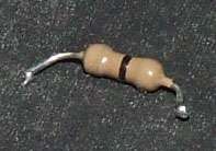
Zero ohm resistors, marked with a single black band,[6] are lengths of wire wrapped in a resistor-like body which can be mounted on a printed-circuit board (PCB) by automatic component-insertion equipment. They are typically used on PCBs as insulating "bridges" where two traces would otherwise cross, or as soldered-in jumper wires for setting configurations.
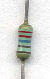
The "body-end-dot" or "body-tip-spot" system was used for cylindrical composition resistors sometimes still found in very old equipment; the first band was given by the body color, the second band by the color of one end of the resistor, and the multiplier by a dot or band around the middle of the resistor. The other end of the resistor was in the body color, silver, or gold for 20%, 10%, 5% tolerance (tighter tolerances were not routinely used).[7][8][9][10]
Capacitor color-coding
Capacitors may be marked with 4 or more colored bands or dots. The colors encode the first and second most significant digits of the value in picofarads, and the third color the decimal multiplier. Additional bands have meanings which may vary from one type to another. Low-tolerance capacitors may begin with the first 3 (rather than 2) digits of the value. It is usually, but not always, possible to work out what scheme is used by the particular colors used. Cylindrical capacitors marked with bands may look like resistors.
| Color | Significant digits | Multiplier | Tolerance [%] | Characteristic | DC working voltage [V] | Operating temperature [°C] | EIA/vibration [Hz] | |
|---|---|---|---|---|---|---|---|---|
| Black | 0 | 1 | — | — | — | −55 to +70 | 10 to 55 | |
| Brown | 1 | 10 | ±1 | B | 100 | — | — | |
| Red | 2 | 100 | ±2 | C | — | −55 to +85 | — | |
| Orange | 3 | 1000 | — | D | 300 | — | — | |
| Yellow | 4 | 10000 | — | E | — | −55 to +125 | 10 to 2000 | |
| Green | 5 | 100000 | ±0.5 | F | 500 | — | — | |
| Blue | 6 | 1000000 | — | — | — | −55 to +150 | — | |
| Violet | 7 | 10000000 | — | — | — | — | — | |
| Grey | 8 | — | — | — | — | — | — | |
| White | 9 | — | — | — | — | — | EIA | |
| Gold | — | — | ±5[nb 4] | — | 1000 | — | — | |
| Silver | — | — | ±10 | — | — | — | — | |
Extra bands on ceramic capacitors identify the voltage rating class and temperature coefficient characteristics.[7] A broad black band was applied to some tubular paper capacitors to indicate the end that had the outer electrode; this allowed this end to be connected to chassis ground to provide some shielding against hum and noise pickup.
Polyester film and "gum drop" tantalum electrolytic capacitors may also be color-coded to give the value, working voltage and tolerance.
Inductor color-coding
Standards IEC 60062 / EN 60062 do not define a color code for inductors, but various manufacturers of physically small inductors utilize the resistor color code for this purpose, typically encoding inductance in microhenries.[11] A white tolerance ring may indicate custom specifications.[11]
Diode part number
The part number for small JEDEC "1N"-coded diodes—in the form "1N4148"—is sometimes encoded as three or four rings in the standard color code, omitting the "1N" prefix. The 1N4148 would then be coded as yellow (4), brown (1), yellow (4), grey (8).
Postage stamp capacitors and war standard coding
Capacitors of the rectangular "postage stamp" form made for military use during World War II used American War Standard (AWS) or Joint Army Navy (JAN) coding in six dots stamped on the capacitor. An arrow on the top row of dots pointed to the right, indicating the reading order. From left to right the top dots were: either black, indicating JAN mica, or silver, indicating AWS paper; first significant digit; and second significant digit. The bottom three dots indicated temperature characteristic, tolerance, and decimal multiplier. The characteristic was black for ±1000 ppm/°C, brown for ±500, red for ±200, orange for ±100, yellow for −20 to +100 ppm/°C, and green for 0 to +70 ppm/°C.
A similar six-dot code by EIA had the top row as first, second and third significant digits and the bottom row as voltage rating (in hundreds of volts; no color indicated 500 volts), tolerance, and multiplier. A three-dot EIA code was used for 500 volt 20% tolerance capacitors, and the dots signified first and second significant digits and the multiplier. Such capacitors were common in vacuum tube equipment and in surplus for a generation after the war but are unavailable now.[12]
Mnemonics
A useful mnemonic matches the first letter of the color code, in numeric order. Here are two that includes tolerance codes gold, silver, and none:
- Bad beer rots our young guts but vodka goes well – get some now.[13]
- B B ROY of Great Britain had a Very Good Wife who wore Gold and Silver Necklace.
The colors are sorted in the order of the visible light spectrum: red (2), orange (3), yellow (4), green (5), blue (6), violet (7). Black (0) has no energy, brown (1) has a little more, white (9) has everything and grey (8) is like white, but less intense.[14]
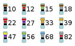
Examples
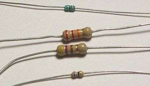
From top to bottom:
- Green, blue, black, black, brown
- 560 ohms ±1%
- Red, red, orange, gold
- 22000 ohms ±5%
- Yellow, violet, brown, gold
- 470 ohms ±5%
- Blue, grey, black, gold
- 68 ohms ±5%
The physical size of a resistor is indicative of the power it can dissipate.
There is an important difference between the use of three and of four bands to indicate resistance. The same resistance is encoded by:
- Red, red, orange = 22 followed by 3 zeroes = 220,00 (excluding default, silver, or gold tolerance)
- Red, red, black, red = 220 followed by 2 zeroes = 22,000 (excluding brown or other band for tolerance)
Transformer wiring color codes
Power transformers used in North American vacuum-tube equipment were often color-coded to identify the leads. Black was the primary connection, red secondary for the B+ (plate voltage), red with a yellow tracer was the center tap for the B+ full-wave rectifier winding, green or brown was the heater voltage for all tubes, yellow was the filament voltage for the rectifier tube (often a different voltage than other tube heaters). Two wires of each color were provided for each circuit, and phasing was not identified by the color code.
Audio transformers for vacuum tube equipment were coded blue for the finishing lead of the primary, red for the B+ lead of the primary, brown for a primary center tap, green for the finishing lead of the secondary, black for grid lead of the secondary, and yellow for a tapped secondary. Each lead had a different color since relative polarity or phase was more important for these transformers. Intermediate-frequency tuned transformers were coded blue and red for the primary and green and black for the secondary.[12]
Other wiring codes
Wires may be color-coded to identify their function, voltage class, polarity, phase or to identify the circuit in which they are used. The insulation of the wire may be solidly colored, or where more combinations are needed, one or two tracer stripes may be added. Some wiring color codes are set by national regulations, but often a color code is specific to a manufacturer or industry.
Building wiring under the US National Electrical Code and the Canadian Electrical Code is identified by colors to show energized and neutral conductors, grounding conductors and to identify phases. Other color codes are used in the UK and other areas to identify building wiring or flexible cable wiring.
Mains electrical wiring, both in a building and on equipment was once usually red for live, black for neutral, and green for earth, but this was changed as it was a hazard for color-blind people, who might confuse red and green; different countries use different conventions. Red and black are frequently used for positive and negative of battery or other single-voltage DC wiring.
Thermocouple wires and extension cables are identified by color code for the type of thermocouple; interchanging thermocouples with unsuitable extension wires destroys the accuracy of the measurement.
Automotive wiring is color-coded but standards vary by manufacturer; differing SAE and DIN standards exist.
Modern personal computer peripheral cables and connectors are color-coded to simplify connection of speakers, microphones, mice, keyboards and other peripherals, usually according to the PC99 scheme.
A common convention for wiring systems in industrial buildings is: black jacket – AC less than 1,000 volts, blue jacket – DC or communications, orange jacket – medium voltage 2,300 or 4,160 V, red jacket 13,800 V or higher. Red-jacketed cable is also used for relatively low-voltage fire alarm wiring, but has a much different appearance.
Local area network cables may also have non-standardised jacket colors identifying, for example, process control network vs. office automation networks, or to identify redundant network connections, but these codes vary by organization and facility.
See also
| Wikimedia Commons has media related to Electronic color code. |
- E-series of preferred numbers — IEC 60063, which defines series of preferred resistance values.
- Color code
- Electrical wiring — AC power wiring inside buildings, including standard color codes
Notes
- 1 2 Before yellow and grey colored rings were assigned to tolerance values of ±0.02% and ±0.01% with IEC 60062:2016, some manufacturers used yellow and grey as substitute for gold (±5%) and silver (±10%) colored rings in high-voltage resistors to avoid metal particles in the lacquer.
- 1 2 Any temperature coefficient not assigned its own letter shall be marked "Z", and the coefficient found in other documentation.
- ↑ Before a grey colored ring was assigned to a tolerance of ±0.01% with IEC 60062:2016, some manufacturers used a grey colored ring to indicate a non-standardized tolerance of ±0.05%.
- ↑ ±5% or ±0.5 pF, whichever is greater.
References
- ↑ EIA
- ↑ EIA RS-279: Color code for film resistors. Electronic Industries Alliance. 1963-08-01.
- 1 2 3 4 5 "IEC 60062:2016-07" (6 ed.). July 2016. Archived from the original on 2018-07-23. Retrieved 2018-07-23.
- ↑ https://tomwwolf.files.wordpress.com/2013/12/mil-hdbk-199c.pdf
- 1 2 VR37 High ohmic/high voltage resistors (PDF). Vishay. 2015. Archived from the original (PDF) on 2016-09-10.
- ↑ NIC Components Corp. NZO series zero-ohm resistors.
- 1 2 Reference Data for Radio Engineers, Federal Telephone and Radio Corporation, 2nd edition, 1946 page 52
- ↑ "How To Read Old Style Resistors" (PDF). 2006-10-03. Archived (PDF) from the original on 2016-12-19. Retrieved 2016-12-19.
- ↑ "RMA Resistor and Flexible Resistor Color Codes". Archived from the original on 2016-12-19. Retrieved 2016-12-19.
- ↑ "The Antique Resistor Color Code" (PDF). Archived (PDF) from the original on 2016-12-19. Retrieved 2016-12-19.
- 1 2 https://en.tdk.eu/download/531410/59a5850434250d35b39a06d5c80bf362/pdf-rfgeneral.pdf
- 1 2 Tony Dorbuck (ed),The Radio Amateur's Handbook Fifty Fifth (1978 edition), The American Radio Relay League, Connecticut 1977, no ISBN, Library of congress card no. 41-3345, pages 553–554
- ↑ The Mnemonics Page – Dean Campbell, Bradley University Chemistry Department
- ↑ Preston R. Clement and Walter Curtis Johnson (1960). Electrical Engineering Science. McGraw-Hill. p. 115.
External links
- Multi-purpose resistor code converter (4 and 5 band, mobile-friendly, shows nearest standard value)
- 6 band resistor color code calculator (easy lookup, 4 and 5 band calculators also available)