Differentiator
In electronics, a differentiator is a circuit that is designed such that the output of the circuit is approximately directly proportional to the rate of change (the time derivative) of the input. An active differentiator includes some form of amplifier. A passive differentiator circuit is made of only resistors and capacitors.
Passive differentiator
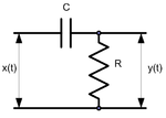
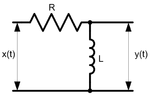
A true differentiator cannot be physically realized, because it has infinite gain at infinite frequency. A similar effect can be achieved, however, by limiting the gain above some frequency. Therefore, a passive differentiator circuit can be made using a simple first-order high-pass filter, with the cut-off frequency set to be far above the highest frequency in the signal. This is a four-terminal network consisting of two passive elements as shown in figures 1 and 2.
Transfer function
The analysis here is for the capacitive circuit in figure 1. The inductive case in figure 2 can be handled in a similar way.
The transfer function shows the dependence of the network gain on the signal frequency for sinusoidal signals.
According to Ohm's law,

where and are input and output signals' amplitudes respectively, and and are the resistor's and capacitor's impedances. Therefore, the complex transfer function is


where

The amplitude transfer function

and the phase transfer function

which are both shown in Figure 3.
Transfer functions for the second circuit are the same (with ).

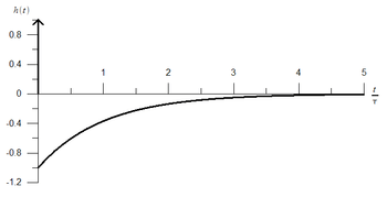
Impulse response
The circuit's impulse response, which is shown in figure 4, can be derived as an inverse Laplace transform of the complex transfer function:

where is a time constant, and is a delta function.


Active differentiator
Ideal differentiator
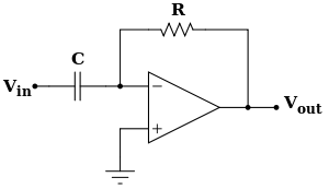
A differentiator circuit (also knows as a differentiating amplifier) consists of an operational amplifier in which a resistor R provides negative feedback and a capacitor is used at the input side. The circuit is based on the capacitor's current to voltage relationship
![{\displaystyle V=V(\infty )+[(V(0+)-V(\infty )]e^{-{\frac {t}{\tau }}},}](../I/m/5db266074f1e7899b2cb44cbaf01fbf68cd4b7ee.svg)

where I is the current through the capacitor, C is the capacitance of the capacitor, and V is the voltage across the capacitor. The current flowing through the capacitor is then proportional to the derivative of the voltage across the capacitor. This current can then be connected to a resistor, which has the current to voltage relationship

where R is the resistance of the resistor.
Note that the op amp input has a very high input impedance (it also forms a virtual ground due to the presence of negative feedback), so the entire input current has to flow through R.
If Vout is the voltage across the resistor and Vin is the voltage across the capacitor, we can rearrange these two equations to obtain the following equation:

From the above equation following conclusions can be made:
- Output is proportional to the time derivative of the input. Hence, the op amp acts as a differentiator.
- Above equation is true for any frequency signal.
- The negative sign indicates that there is 180° phase shift in the output with respect to the input,
Thus, it can be shown that in an ideal situation the voltage across the resistor will be proportional to the derivative of the voltage across the capacitor with a gain of RC.
Operation
Input signals are applied to the capacitor C. Capacitive reactance is the important factor in the analysis of the operation of a differentiator. Capacitive reactance is Xc = 1/2πfC. Capacitive reactance is inversely proportional to the rate of change of input voltage applied to the capacitor. At low frequency, the reactance of a capacitor is high, and at high frequency reactance is low. Therefore, at low frequencies and for slow changes in input voltage, the gain, Rf/Xc, is low, while at higher frequencies and for fast changes the gain is high, producing larger output voltages.
If a constant DC voltage is applied as input, then the output voltage is zero. If the input voltage changes from zero to negative, the output voltage is positive. If the applied input voltage changes from zero to positive, the output voltage is negative. If a square-wave input is applied to a differentiator, then a spike waveform is obtained at the output.
The active differentiator isolates the load of the succeeding stages, so it has the same response independent of the load.
Frequency response
_of_an_Ideal_Differentiator.png)
Advantages
A small time constant is sufficient to cause differentiation of the input signal.
Limitations
At high frequencies:
- this simple differentiator circuit becomes unstable and starts to oscillate;
- the circuit becomes sensitive to noise, that is, when amplified, noise dominates the input/message signal.
Practical differentiator
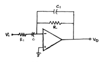
In order to overcome the limitations of the ideal differentiator, an additional small-value capacitor C1 is connected across the feedback resistor R, which avoids the differentiator circuit to run into oscillations (that is, become unstable), and a resistor R1 is connected in series with the capacitor C, which limits the increase in gain to a ratio of R/R1.
Since negative feedback is present through the resistor R, we can apply the virtual ground concept, that is, the voltage at the inverting terminal = voltage at the non-inverting terminal = 0.
Applying nodal analysis, we get


Therefore,

Hence, there occurs one zero at and two poles at and .


Frequency response
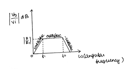
From the above plot, it can be seen that:
- when , the circuit acts as a differentiator;
- when , the circuit acts as a voltage follower or buffer;
- when , the circuit acts as an integrator.


If (say), there occurs one zero at and two poles at .


For such a differentiator circuit, the frequency response would be
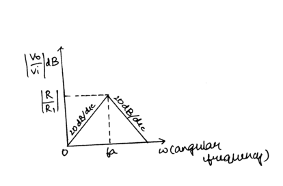
From the above plot, we observe that:
- when , the circuit acts as a differentiator;
- when , the circuit acts as an integrator.


Applications
The differentiator circuit is essentially a high-pass filter. It can generate a square wave from a triangle wave input and produce alternating-direction voltage spikes when a square wave is applied. In ideal cases, a differentiator reverses the effects of an integrator on a waveform, and conversely. Hence, they are most commonly used in wave-shaping circuits to detect high-frequency components in an input signal. Differentiators are an important part of electronic analogue computers and analogue PID controllers. They are also used in frequency modulators as rate-of-change detectors.
A passive differentiator circuit is one of the basic electronic circuits, being widely used in circuit analysis based on the equivalent circuit method.
See also
- Integrator
- Inverting differentiator at op amp applications