Bank engine

A bank engine (United Kingdom/Australia) (colloquially a banker) or helper engine or pusher engine (North America) is a railway locomotive that temporarily assists a train that requires additional power or traction to climb a gradient (or bank). Helpers/bankers are most commonly found in mountain divisions (called "helper districts" in the U.S.), where the ruling grade may demand the use of substantially greater motive power than that required for other grades within the division.
Historic practice

Helpers/bankers were most widely used during the age of steam, especially in the American West, where significant grades are common and trains are long. The development of advanced braking systems and diesel-electric or electric locomotives has eliminated the everyday need for bankers/helpers in all but a few locations. With the advent of dynamic brakes on electric or diesel-electric locomotives, helpers/bankers can also be used to provide more braking force on long downhill gradients.
Bankers or helpers were historically positioned at the rear of the train, in which case they also protected against wagons or coaches breaking away from the train and running back downhill. Also, in a pusher role, it was possible for the helper/banker to easily separate once the train had crested the grade. Once separated, the banker would return to a siding or stub so as to clear the mainline and get ready for the next train. A common practice with knuckle couplers was to remove the knuckle from the front coupler. The locomotive would be brought up behind the last car of the train while the train was moving slowly. The air brake hose would not be coupled. When the train no longer required assistance, the helper/pusher would slow, then reverse and coast back down the grade to its siding at the bottom of the grade. This practice was outlawed in North America after the end of the steam era.
Special heavily constructed cabooses were sometimes used in helper areas. Ordinary cabooses were built as lightly as practical and might be crushed by the helper/pusher's force, which could be as much as 90 tons. The heavy cabooses allowed crews to avoid the time-consuming procedure of splitting the train just ahead of the caboose.[1]
Pushers/helpers were commonly designed to provide extreme power for very short runs; as a result they could not push at full power for very far before steam pressure dropped. But if it could push enough to get the train to the top of the grade, then it could build up pressure while coasting back down and while waiting for the next train to come along. This practice was common in Europe.
Since it was not possible to remotely control a steam locomotive, each helper had to have a full crew on board. Careful coordination was required between engine crews to assure that all locomotives were operated in a consistent manner. Standard whistle signals were employed to tell the helper crew when to apply power, drift or brake. A misunderstanding of signals by a pusher locomotive crew could result in a major wreck if the lead locomotive applied brakes while the bank engine was still applying power. The usual result was that the train would experience a violent run-in (an abrupt bunching of train slack), resulting in the derailment of part or all of the train.
The town of Helper, Utah was named after these engines, as it was where helper engines were kept to assist on the climb to Soldier Summit.
Modern practice
Nowadays helpers/bankers are often controlled by coded radio signals from the locomotive at the head end of the train, allowing one engineer (driver) to simultaneously control the helper(s) and the train being helped. If radio operation is not possible, electrical control might be used, by way of cables running the length of the train (especially in case of passenger trains), or else the helpers are manually controlled, which is still the norm for bank engines at the end of freight trains in Europe.
At the front
In the UK, an engine that was temporarily attached to the front of a train to assist with the ascent of an incline was called a pilot locomotive. This differentiated it from the train engine(s) which was provided to power the train to its destination. A train with one or more helper locomotives attached to the front may be referred to as a "double header", "triple header", etc., depending on the number of helpers/bankers. These terms gradually fell out of general usage as diesel locomotives replaced steam power.
Mid-train
In countries where buffers-and-chain couplers are used, bank engines often cannot be added to the front of the train due to the limited strength of the couplers; In the case of standard UIC couplers and a maximum grade of 28‰ (which is common e.g. for lines through the Alps), the limit is a train weight of 1400 tons;[2] if a train is heavier, bank engines have to be added in the middle or to the end of the train in order not to exceed the maximum load for any coupler.
Adding locomotives in the middle of the train has the distinct advantage of applying the helper power to only part of the train, thus limiting the maximum drawbar pull applied to the first car of the train to a safe level. The narrow gauge portions of the Denver and Rio Grande Western Railroad, in particular, used "swing helpers", which meant the helper locomotives were placed mid-train at a point where they were pushing and pulling an approximately equal amount of tonnage, said location being referred to as the train's "swing point". This was also done to balance out the "slack" in the train between the locomotives, the swing helpers, and the end train helpers just in front of the caboose. However, this arrangement requires splitting the train in order to add or remove the helper engine(s), which can be a time-consuming maneuver. However, on some American railroads it was necessary to an extent because operating rules required end of train helpers to be added at the end of the train, but in front of the caboose. This was done for the safety of the train crew riding inside the caboose.
End of the train
To be able to add and remove helper locomotives quickly, which is especially important in Europe due to the high traffic density, they are usually added to the end of the train. Normally they are coupled and the air hoses are connected, which is necessary for the air brake to work correctly e.g. in emergency situations, but in special cases trains are banked with uncoupled locomotives, which can be added or removed "in-flight." In the UK it was a usual practice for banking locomotives to follow and buffer-up to a slow-moving assisted freight train without coupling (as demonstrated in archive films of banking on the Lickey Incline) before applying more power, thus avoiding a standing start. This procedure is not performed in North America as it would violate Canadian and US safety regulations.
Examples
The following are locations where bankers are, or were, frequently required. Note that different regions of the world express grades differently, commonly used are ‰ (per mill), % (per cent), or a fractional ratio.
Austria
- Arlberg railway (33‰) between Landeck and Bludenz
- Brenner railway (25‰) between Innsbruck or Wörgl and Brenner Pass
Australia
New South Wales
- Willow Tree - Ardglen - 2.5% (1 in 40)
- Murrurundi - Ardglen - 2.5% (1 in 40)
- Cowan bank - 2.5% (1 in 40) (double track) (4 tunnels)
- Georges Plains - Wimbledon - 2.5% (1 in 40)
- Tumulla - crossing loop on 2.5% (1 in 40)
- Fassifern - 2.5% (1 in 40) - bank engine key interlocked with bank engine siding. (double track)
- Bathurst - Kelso - 2.0% (1 in 50) (double track)
- Lawrence Road - 2.0% (1 in 50)
- Lithgow - Zig Zag - 2.4% (1 in 42) (double track)
- Valley Heights - Katoomba - 3.0% (1 in 33)
- Molong - Orange - 2.5% (1 in 40)
- Picton Mittagong Loop Line - 3.0% (1 in 33)

Canada
- Crowsnest Pass – Canadian Pacific Railway
- Eagle Pass – Canadian Pacific Railway
- Kicking Horse Pass – Canadian Pacific Railway
- Rogers Pass – Canadian Pacific Railway
- Squamish, BC to Prince George, BC; essentially the entire mainline – British Columbia Railway – notable for use of mid-train helper locomotives and helpers on the rear, all operated by radio control from the leading locomotives.
China
- Boketu–Taerqi Railway (42.5‰)
- Baoji–Chengdu Railway, Baoji - Qinling section (Crossing the Qinling Mountains, 33.5‰)
- Southern Xinjiang Railway (Crossing the Tian Shan, 22‰)
- Qinghai–Tibet Railway (Tibetan Plateau, 20‰)
Belgium
- Liège-Guillemins - (32 ‰) Banking of some hauled passenger trains heading towards Brussels between Liège-Guillemins and Ans. Freight trains are not allowed on this section.
France/Italy
- Maurienne Valley line, the main line from France to Italy through the Alps - Frequent electric banking services for freight trains - 30‰ .
Germany
- Spessart Ramp between Aschaffenburg and Würzburg in northern Bavaria
- Schiefe Ebene between Neuenmarkt-Wirsberg and Marktschorgast in Northern Bavaria
The Royal Bavarian Railways developed special 0-8-8-0 mallet banking locomotives: series Gt 2×4/4
- Geislinger Steige on the line Stuttgart-Ulm in Württemberg
- Erkrath - Hochdahl on the line Düsseldorf - Wuppertal
India
- Jammu Tawi towards Udhampur and Katra, Jammu and Kashmir.
- Lalkuan towards Kathgodam, Nainital in Uttarakhand.
- Karjat towards Lonavala in Western Ghats.
- Kasara towards Igatpuri in Western Ghats.
- Kulem, Goa towards Castlerock, Karnataka in Western Ghats.
- Kukke Subramanya towards Sakleshpur, Karnataka in Western Ghats, Green Route between Mangaluru and Bengaluru
- Patalpani towards Kalakund in Madhya Pradesh.
- Dharakhoh towards Maramjhiri in Satpura Range.
Italy
- Opicina Tramway in Trieste - bankers on a 260‰ funicular section of the line
Japan
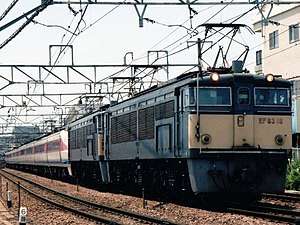
- "Senohachi" section (Seno - Hachihommatsu) of the Sanyo Main Line - Dedicated JNR Class EF67 and EF210-300 electric locomotives assist heavy freight trains from the rear.
- Usui Pass on the Shinetsu Line - The maximum grade of 66.7‰ (1 in 15) necessitated the use of helper locomotives on all trains, including EMUs, both uphill and downhill (for added braking ability). A pair of JNR Class EF63 electric locomotives were coupled at the downhill side of every train. This segment was closed upon the opening of the Nagano Shinkansen in 1997.
Mexico
New Zealand
- Reefton saddle on the Stillwater - Westport Line
- Wellington and Manawatu Railway Company between Wellington and Paekakariki; the Johnsonville Line section bypassed by the Tawa Flat deviation (1 in 40) and also the Pukerua Bank to Pukerua Bay from Plimmerton (going north; 1 in 57) and Paekakariki (going south; 1 in 66).
- North Island Main Trunk between Taumarunui and Taihape
- Otira Tunnel, between Arthur's Pass and Otira on the Midland Line - 30‰ (1 in 33)
Steam banking engines used included the NZR Wj class of 1904 and NZR E class (1906).
Banking by diesel-electric locomotives is also used on all steam train excursions that travel between Tauranga and Matamata on the East Coast Main Trunk, Featherston and Upper Hutt on the Wairarapa Line, and Arthur's Pass and Otira on the Midland Line. This is due to steam operation being too dangerous within the confinements of long tunnels on those sections of line.
Pakistan
- Bolan Pass Railway between Aab-i-Gum and Kolpur
- Khyber Pass Railway
Sri Lanka
- Upcountry line - To climb 1:44 ratio incline between Rambukkana to Kadugannawa and from Nawalapitiya to Pattipola, when returning Badulla to Pattipola, for Night Mail train
Switzerland
- Gotthard line - 27‰. Frequent electric banking services for freight trains, SBB-CFF-FFS and others
- Lötschberg line - 27‰. Frequent electric banking services until the opening of the Lötschberg Base Tunnel in June 2007; now most of heavy trains use the base tunnel (maximum 15‰ on northern approach) and bank engines are less frequently used; BLS, SBB-CFF-FFS and others
- Südostbahn between Pfäffikon SZ and Arth-Goldau - 52‰. Electric banking services (using locomotives or EMUs) often necessary when the Voralpenexpress has additional coaches
- Monte Ceneri Pass line (part of the Gotthard line) - 28‰ northern ramp, 20‰ southern ramp. Frequent electric banking services, SBB-CFF-FFS and others
United Kingdom
- The 'Long Drag' to Aisgill Summit on the former Midland Railway Settle-Carlisle Line required the use of pilot engines in both directions during the steam era.
- Beattock Bank on the former Caledonian Railway section of the West Coast Main Line. Prior to electrification banking engines were required for northbound trains (from Beattock station to Beattock Summit).
- Cowlairs Bank, outside Glasgow Queen Street station is short but steep (2.4%, or 1 in 42), and much of it is in a tunnel. Cable worked until 1909, the use of banking locomotives finally ended in the 1980s.
- Druimuachdar Summit on the Highland Main Line
- Ilfracombe branch line (2.8%, or 1-in-36) – Steam until 1964
- Falahill Bank on the northern part of the former North British Railway 'Waverley Route'. Banking engines were required for southbound trains (from Hardengreen Junction, near Dalkeith, to Falahill Summit)
- Lickey Incline, where banking of goods trains by EWS class 66 locomotives still occurs.
- Peak Forest, Derbyshire – Steam then diesel until the late 1980s
- The Buxton Line in Derbyshire
- Slochd Summit on the Highland Main Line
- Severn Tunnel on the South Wales Main Line, from Severn Tunnel Junction to Patchway
- Shap on the former London and North Western Railway section of the West Coast Main Line, required banking of northbound trains in the steam era
- On the Somerset & Dorset Joint Railway, southbound goods trains were banked from Bath to the summit at Combe Down Tunnel, and also from Radstock to Masbury Summit, while northbound trains were banked from Evercreech Junction to Binegar. Passenger trains in both directions usually used a pilot engine.
- South Devon banks at Dainton on the Exeter to Plymouth Line
- Whiteball/Wellington Bank, Somerset on the route to Exeter
- Whitrope Summit on the former North British Railway 'Waverley Route' (closed in 1969). Banking engines were employed in both the southbound direction (from Hawick), and northbound (from Newcastleton)
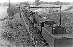 Westbound coal train on Worsborough Incline, with two banking engines, ex-GC Robinson J11 No. 64374 and ex-WD 2-8-0 No.90709 in August 1950
 - Worsbrough Bank (also known as the Wentworth Incline), South Yorkshire, on the Worsborough branch of the Woodhead Line – Steam until 1953 then electric until 1981 - nominally 2.5% (1 in 40) but steeper in parts due to colliery subsidence
United States
.jpg)
- Bozeman Pass - Montana Rail Link
- Byron Hill - Canadian National, ex-Wisconsin Central Limited, originally Soo Line
- Cajon Pass – BNSF Railway, ex-Atchison, Topeka, and Santa Fe; Union Pacific
- Cima Hill – Union Pacific, 2.2% grade, Kelso, California
- Cowan, Tennessee, Cumberland Mountain Tunnel, CSX, ex-Seaboard System, ex-L&N, originally N.C.&St.L.
- Crawford Hill, Nebraska- BNSF's Nebraska helper district climb with twin horseshoe curves.[5][6] Helpers are based in the nearby town of Crawford.[7]
- Cuesta Grade – Union Pacific, ex-Southern Pacific
- Donner Pass – Union Pacific, ex-Southern Pacific, originally Central Pacific
- Gallitzin Summit – Norfolk Southern, ex-Conrail, ex-Penn Central, ex-Pennsylvania Railroad
- Marias Pass – BNSF Railway Company, ex-Burlington Northern, originally Great Northern
- Moffat Tunnel Line – Union Pacific, ex-Denver and Rio Grande Western
- Mullan Pass – Montana Rail Link, ex-Burlington Northern, originally Northern Pacific
- Raton Pass – BNSF Railway Company, ex-Atchison, Topeka, and Santa Fe
- Saluda Grade – Norfolk Southern, ex-Southern Railway. The steepest mainline railroad grade in North America at 5.03%. Currently out of service. The trailing end of a three car passenger train would be completely above the locomotive.
- Sand Patch Grade – CSX Transportation, ex-Chessie System, originally Baltimore & Ohio,
- San Gorgonio Pass – Union Pacific, ex-Southern Pacific
- Snoqualmie Pass – Milwaukee Road
- Soldier Summit – Union Pacific, ex-Denver and Rio Grande Western
- Stevens Pass – BNSF Railway, ex-Burlington Northern, ex-Great Northern
- Tehachapi Pass – Union Pacific, ex-Southern Pacific; BNSF, ex-Atchison, Topeka, and Santa Fe
- Tennessee Pass – Union Pacific, ex-Denver and Rio Grande Western
- Thayer North Sub – BNSF Railway helpers out of Springfield, MO
Accidents
See also
Notes
- ↑ Source: photo of reinforced outside braced caboose: Richard E. Prince, NC&StL History & Steam Locomotives, p. 73.
- ↑ "Technical description by a Swiss train driver (German)". lokifahrer.ch. Retrieved 13 April 2018.
- ↑ Ferrocarriles Nacionales de Mexico, Horario Numero 4, 6 de Septiembre de 1977
- ↑ Ferrosur, Horario Numero 1, Febrero 1 de 2001.
- ↑ http://www.trainvideodepot.com/DVD-Crawford-Hill-Revisted-Highball_HBCH-DVD
- ↑ Archived July 5, 2011, at the Wayback Machine.
- ↑ "intermodal's Photo Galleries at". Pbase.com. Retrieved 2014-05-23.
External links
- Ghost Depot's entry for Soldier Summit. This page has a photo of a 4-header train with rear helper on the western approach to Soldier Summit