Overview:
This tutorial provides instruction which could be considered formulaic for modeling a basic helicopter via box modeling. Though primarily directed towards users of Wings 3D, the same concepts can be applied to any modeling program that employs box modeling and Catmull Clark subdivision as a construction method. The version of Wings 3D used is 0.98.35, there may be better tools available in subsequent releases which are not employed here. Likewise this instruction may show features not available in earlier and older versions. Even though this tutorial is fairly basic, it may not point out every detail or concept in the program. Hints for default keyboard shortcuts will be in bold capitals. You should familiarize yourself with the general features and operations described in the Wings 3D manual before starting if you haven't done so already.
Fuselage
Step 1: start with a cube
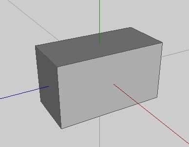
Start with a cube. This will be the fuselage. Elongate it by scaling along the Z axis.
Step 2: Develop form by adding loops
Select the edge rinG consisting of vertical edges and Connect.
Step 3: Block out the cab shape

Create another loop around the middle using method as described in the previous step.
Extrude out the nose. Slide or move edges to get the approximate shape.
Step 4: Tail boom

Using extrude, scale|uniform, and move, create the tail boom as shown.
Alternately, you can use inset and move to acomplish the same result.
Step 5: Centerline loop
Now would be a good time to add the centerline.
You should know the method of adding such edge loops by now.
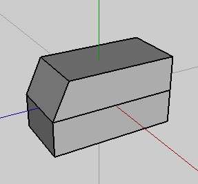
Step 6: Round the front

Select the edges on the front of the windshield and nose and move them forward.
This will make the desired curvature when smoothing.
This is what it looks like so far using smooth preview. (Shift + Tab)
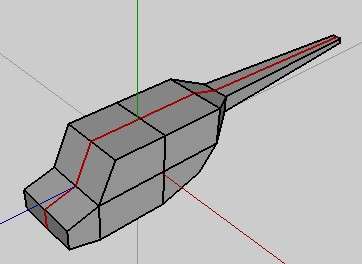
Step 7
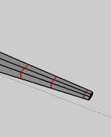
From the smooth preview before, the tail boom ended up looking a little odd.
Add edge loops to help control the smoothing as demonstrated in the picture.
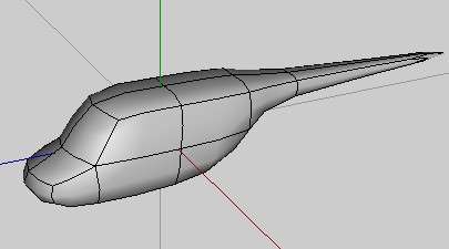
Step 8
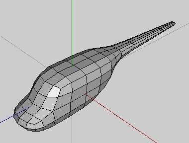
Smooth the model. It should appear similar to the example.
Note the subtle difference in the extra edges in the previous step caused in the tail.
Now there are extra surfaces to work with in later steps.
Step 9: Vertical stabilizer
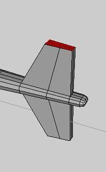
Select faces near the end on the top and bottom of the tail boom.
Extrude region|normal, scale axis|Z, and move|Z to create the vertical stabilizer.
Step 10: Horizontal stabilizer
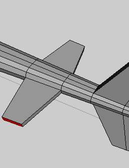
Now find some faces further forward on the tail boom and extrude out the horizontal stabilizers.
Step 11: Place conrol edges and adjust
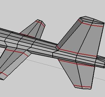
Add edges to conrtrol future smoothing (shown selected.)
A handy technique to use for "control edgeloops" is the double-slide.
This is done by sliding to the extreme in relative mode, and then making another adjustment in absolute mode.
(Note the information on the lower right status area of the Wings3d window.)
This is also a good time to make airfoil shape adjustments to the stabilizers.
Step 12: Adding engine hump
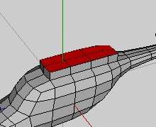
Select faces on top of the cab and extrude region as in the picture.
This creates the engine compartment hump.
Step 13
Move and/or slide edges on the engine hump to give it a nicer shape.
Step 14

Add edges to the engine hump. (shown selected)
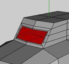
Step 15: Intake nacelle

Select these faces and extrude region by 0 units.
Step 16
Without deselecting faces from the previous step, hit L for Loop.
This will select the edge loop around the region of selected faces. Then slide.
You may need to make some other adjustments to square it up.
Step 17
Select the faces inside the loop again.
Extrude inward to form the air intake nacelle.
Step 18
Select all faces inside the nacelle. (Might be simple as hitting the + key.)
Extrude region|normal a small amount. This will help control any future smoothing.
Step 19: Exhaust port
Repeat the same process used to make the intake nacelle to make the exhaust opening.
Step 20: Rotor shaft opening
Select a vertice on top of the engine hump and bevel.
You may have to move or slide some edges to place the vertice in a suitable position before beveling.
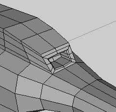
Step 21

Cut edges around bevel and connect to surrounding vertices as shown in the picture.
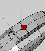
Step 22
Select the vertices around the bevel that was made earlier.
(Select face inside and switch to vertice mode.)
Use Deform|Inflate and adjust to 100%.
It should make a circle as in the example.
Step 23
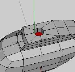
Select the face of the circle you just made and extrude it inward.
This will be the hole for the main rotor shaft.
Step 24
Select all faces inside the hole and extrude region by a small amount.
Step 25

Inset and collapse bottom face to form a star.
Then add an edgeloop inside the side.
Set selected edges in picture to hard.
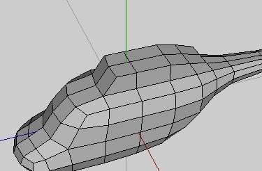
Step 26
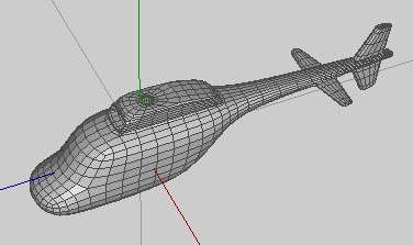
Select the fuselage body and Smooth.
You should have something akin to what is in the example picture.
While in body mode, this is now a good time to rename it to "Fuselage"
instead of "Cube1" if you haven't done so already.
We'll probably not mess with the fuselage again until texturing time.