Space transport generally involves the application of forces to get to a desired location. The comprehensive listing of space transport methods found in Part 2 of this book can be categorized in two dimensions, as shown in the "Table of Space Transport Methods" at the start of that section. The X (horizontal) dimension is how the motive force is applied, and Y (vertical) dimension is the source of the energy used. (See also Spacecraft Propulsion at Wikipedia for another list of methods.) This section will discuss the forces, and section 1.4 Energy Sources will discuss the energy sources. Transport methods can also be categorized by parameters like state of development, exhaust velocity, or efficiency. Section 2.11 - Comparisons will consider these other parameters. We list all known forces considered for transport, without regard to practicality or state of development. How to select the best option for a given transport task will be covered later.
Propulsive forces can be divided into two large groups. The first group develop reaction forces from internal material which is expelled from the vehicle. The second group are forces generated by interacting with an entity outside the vehicle. The law of conservation of momentum (i.e the sum of changes in mass times velocity for the parts of a system is zero) requires that the force you impart to the object you want to move is matched by an equal and opposite force on something else. That something else can be mass you expel from the object, or an outside entity, but in either case the combined forces must be zero.
Reaction from Expelled Mass
Vehicles which use this type of force production are generally called Rockets, and the devices which expel the materials are generally called Engines or Rocket Engines. Specific types each have a descriptive or or common name noted later in the book where they are discussed. The forces generated by an expelled material are derived from Newton's Laws. Where F is force, dm/dt is amount of mass expelled per time, and ve is exhaust velocity, the force can be found by

For accelerating vehicles, we call the force Thrust and give it the symbol T. From this equation we can see the possible ways to increase thrust are (1) increase the mass flow rate, (2) increase the exhaust velocity, or (3) some combination of both. The available material to expel, also known as Reaction Mass or Propellant, is finite when coming from an internal source. So it is usually preferable to increase velocity to get more total performance. Because this type of propulsion system is self-contained, it can operate in many environments, particularly the vacuum of space.
Exhaust Velocity
A parallel, unidirectional flow has all the mass expelled in a single direction. An expanding gas is generally emitted as a cone with some angular width (see Figure 1.3-1). Molecules not moving parallel the axis of the cone only contribute the parallel component of their motion parallel to the reaction force. This component is found from the cosine of the angle of motion times the molecular velocity. Molecules in an expanding gas also have a range of velocities determined by their temperature and how the flow was shaped. The average axial component over the whole flow is called the Exhaust Velocity. A derived unit is Specific Impulse. Where T is thrust, is propellant flow rate, and g is standard Earth gravity it is defined as


The units for specific impulse are in seconds, and are interpreted as how many seconds one unit of fuel can produce one unit of thrust at 1 gravity. As an example, the high energy propellant combination of produces a specific impulse of about 450 seconds. Exhaust velocity in meters/second is is the preferred SI unit, since that is not Earth-centric by using the level of Earth gravity in the calculation.

In the list that follows, the approximate range of exhaust velocities is noted, and the list is generally in increasing order. Note that what we mainly use today (combustion gas) is among the lowest in performance. To achieve higher mission velocities than the characteristic exhaust velocity you can use large amounts of propellent, stack multiple stages of the same method, or use multiple different methods.
A. Bulk Solids (0-10 km/s)
Solid pellets or slugs are expelled via mechanical devices such as a rotary centrifuge, or an electromagnetic accelerator such as the Mass Driver Reaction Engine. The advantage is being able to use nearly any solid material as the reaction mass. One disadvantage is the relatively low exhaust velocity compared to Ion and Plasma engines. The extra work in extracting a suitable fuel for the latter types is usually much less than the gain from using 5-10 times less reaction mass. Another is the creation of a debris impact hazard by emitting large numbers of uncontrolled objects. A centrifuge or mass driver launching bulk mass from a body which is collected in orbit does not create the same impact hazard, even though it uses the same kind of devices. Mechanical devices are like centrifuges are limited to fairly low velocity, and have not generally been considered for space transport.
B. Microparticles (0 - 4 km/s)
In addition to using bulk solid, finely powdered solid microparticles or droplets such as from inkjet type devices may be accelerated by electrostatic forces after giving them an electrical charge. Advantages of this method are using unprocessed rock dust or single fluids, and enabling very small engines. Compared to bulk solids, microparticles or droplets are less of an impact hazard, though they may pose a contamination problem. Disadvantages include only working well in a vacuum or a very low density non-conducting medium. Any appreciable outside pressure would stop the microparticles by drag or collision. Relative to ion engines, the charge to mass ratio is lower, so the same electrostatic voltages result in lower exhaust velocity and less performance.
C. Gas Flow (0.1 - 10 km/s)
While in theory you can eject a liquid to obtain thrust, in almost all cases better performance can be gotten using a gas. This is due to the higher average molecule velocity and ability to extract energy from the gas expansion. So liquid is skipped among the solid-liquid-gas states of matter as a reaction method. However liquids are a useful as a way to store reaction mass due to higher density and lower vapor pressure. Higher pressures require more storage tank mass.
Gas flow includes ambient temperature gas such as the Nitrogen "cold gas" thrusters used in spacesuit maneuvering backpacks. Cold gas thrusters are useful when you don't want to damage hardware with a hot or chemically reactive exhaust plume, but they are very low performance (~0.5 km/s). Heating a low molecular weight gas (i.e. Hydrogen) allows much better performance due to the higher average molecule velocity. At sufficiently high temperature (around 3000K) the Hydrogen molecules will start to decompose to individual atoms, further increasing velocity. There are numerous possible methods of heating the gas, including electric discharge through the gas (arcjet), concentrated sunlight (solar-thermal), electric filament heaters (resistojet), or heat from a nuclear reactor (nuclear-thermal).
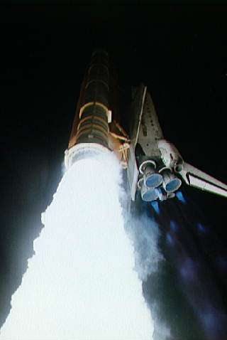
D. Combustion Gas (2 - 5 km/s)
In this method, hot gas is generated by chemical reactions in the propellant. For rockets the hot gas is expelled via a supersonic expansion exit nozzle. That type of nozzle produces the highest velocity in a narrow stream. Performance is limited by the reaction energy in the propellant, which is a maximum of about 15 MJ/kg for non-exotic fuel combinations. This provides a maximum of 5.5 km/s exhaust velocity in theory, and 4.5 km/s in practice. For atmospheric jet engines, some of the energy in the gas is used to drive a turbine and bypass fan blades, which greatly increases the affected mass flow. The remainder is expelled by a nozzle, but the nozzle is typically a simpler geometry. The use of external oxygen extracted from the air flow, and bypass air for mass flow, dramatically reduces the rate of fuel use, but also limits the flight velocity due to drag and heating.
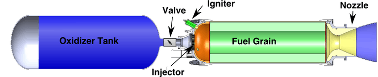
There are several types of combustion gas rockets. A Monopropellant has a single ingredient which is decomposed and heated by passing over a catalyst bed. A Bi-Propellant has two ingredients, a fuel and an oxidizer, which are generally mixed and burned in a Combustion Chamber. In a Liquid Rocket the two ingredients are stored in liquid form in separate propellant tanks, although one or both may be converted to gas before reaching the combustion chamber. In a Hybrid Rocket one of the ingredients is in solid form (usually the fuel), and the other in liquid form. In a Solid Rocket all the ingredients are in a finely mixed powder which has been cast into a solid form. A typical solid rocket formulation has an oxidizer like Ammonium Perchlorate (NH4ClO4), and a complex fuel containing powdered aluminum, rubber, and epoxy, which both binds all the ingredients together and is part of the fuel being burned.
There are a large number of combinations of form and fuel mixtures for rockets, but only a few are used with any frequency. Because of the high thrust-to-mass ratio and ability to work in many environments, combustion gas systems have been by far the most popular for space transport so far, and almost exclusively the one for launch to Earth orbit. Their disadvantage is that the exhaust velocity of the best propellants is about half the necessary velocity, including various losses, to reach Earth orbit. Solving the Tsiolkovsky Rocket Equation (section 1.2), we find the mass ratio is at least 7.4, which leaves only 13.5% of liftoff mass for the vehicle and payload. The best propellant includes liquid Hydrogen as the fuel, which is very low density, so keeping the vehicle mass low enough for reasonable payload is difficult. If a denser and lower performance fuel is chosen, less structural mass is needed for propellant tanks, but the mass ratio is higher. This still leaves small payload mass. Until now, the solution has mainly been to use the rocket once, which allows lighter hardware, and discarding part of the hardware once some of the propellant has been used (staging). This is an expensive solution. For the future, a better approach is to move away from chemical rockets and their limited fuel energy in relation to what is needed to leave Earth. That will allow more of the vehicle mass to be hardware and payload, and less to be fuel. Designs can then be more robust and used many times, and the cargo can be a larger fraction of liftoff mass. The combination will drastically reduce costs.
E. Plasma (5 - 200 km/s)
In this category the propellant is heated to the point that the atoms disassociate into charged components (ions and electrons), then directed out of the Plasma Engine with magnetic fields. Heating can be accomplished by a vigorous electric discharge, intense microwaves, laser, or internal heating in a fusion plasma. Plasmas are hot enough to melt most materials, including the ones used for the rest of the engine, so they are usually contained by a magnetic field. Alternately the plasma density (and hence the thrust) can be kept low enough that the engine can disperse the heat gained. There is no theoretical limit to how hot a plasma can be. Since the kinetic energy of the exhaust increases as the square of the velocity, there is a practical limit based on how much energy you can supply. Plasmas can be physically confined by magnetic fields, but they also emit light that escapes to their surroundings. The surface of the Sun, for example, is a 5780 K plasma. So heating of the engine components will also limit a practical design. Many plasma confinement techniques derive from fusion research, which deals with extremely hot plasmas. Recent development of superconducting coils improves their efficiency, so design of effective plasma engines is fairly recent. Because their exhaust velocities can be ten or more times higher than for combustion gas, plasma engines are in active development, but have not reached operational use as of 2016.
F. Ions (2 - 200 km/s)
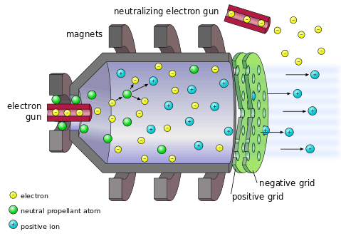
Ions are atoms from which one or more electrons have been removed. In an Ion Engine the propellant is first ionized using electron bombardment or RF oscillations (Figure 1.3-4). The positive ions, which represent nearly all the mass, are accelerated across a voltage gradient to high velocity. The voltage gradient can be a set of metal screens, or a charged plasma. To maintain overall charge balance across the vehicle, an electron gun separately emits negative charges, or the ions recombine in the charged plasma. Once outside the engine the combined emission is electrically neutral so that the vehicle does not accumulate a net charge. Compared to a plasma, an ion beam is generally lower density, so requires lower power levels to operate and generates lower thrust. The main difference is creating high ion velocity via electric forces rather than heating. Efficiency in converting power to thrust is similar (60-75%), as is maximum exhaust velocity. Like plasma engines, the energy required rises as the square of exhaust velocity. Practical limits on the power source then limits performance. Because ion engines can operate with less overhead in small sizes than plasma engines, and are derived from vacuum tube technology, they were developed earlier.
Ion engines are in use, as of 2016, on many communications satellites, and a few planetary spacecraft where high total mission velocity is needed. In the future we expect their use to increase, along with the larger plasma engines, because they use an order of magnitude less propellant than chemical rockets. In addition, the last 20 years has seen the development of lightweight and efficient solar panels to provide power for them. Their disadvantage is low thrust, so they cannot be used on their own for launch or landing on large bodies. This can be overcome by combining them with other methods.
G. Atomic Particles (1000 km/s to near c)
Atomic particles include nuclei of atoms from which all electrons have been removed, single electrons, neutrons, or protons, or more exotic particles such as muons. Whereas an ion engine typically uses a single voltage gradient, a particle accelerator has multiple chambers that add successive amounts of energy to the particles. This enables exhaust velocities up to near the speed of light, c , or 299,792 km/s. Another method is direct emission of atomic particles from fission decay, fusion reactions, or antimatter decay. These have particle velocities that are a significant fraction of c. Charged particles (generally those besides neutrons) can be directed by magnetic or electric fields, while neutral particles must be allowed to leave in one direction and absorbed in the others to produce net thrust. Although accelerators on Earth have reached very close to c, which is the universal speed limit, no space mission has yet required this high a performance. So this reaction method remains theoretical at present.
In this category is the Bussard Ramjet concept, which is a kind of fusion rocket. Rather than carry all the fuel on-board, it uses a huge electromagnetic field as a ram scoop to collect and compress hydrogen from the interstellar medium. The field compresses the hydrogen until fusion occurs, then directs the energy as rocket exhaust, accelerating the vessel. The difference between the incoming interstellar gas pressure and outgoing exhaust provides the thrust. The Bussard Ramjet currently has conceptual difficulties and is very far from being used.
H. Photon Emission (1.0c exactly)
Photon momentum is calculated by E/c, where E is the energy and c is the speed of light. Thrust is then P/c where P is the power of the emission. Direct emission of photons, while low in thrust, has the highest possible exhaust velocity. For practical use, an extremely high energy source needs to be used, such as fusion or antimatter decay. Fairly simple thermal (black body) emission and reflector arrangements can align the light beam to produce useful thrust. A laser aligns the light very accurately, but the gain is small compared to a light beam with a width of a few degrees. The momentum contribution for an off-axis photon is cosine(a), where a is the off axis angle. For small angles that is very close to 1.0. Like atomic particles, no space transport mission has needed this high a performance, so it is a theoretical method at present.
Unbalanced photon emission as an incidental effect has been noted for the Pioneer spacecraft and with respect to small asteroids, where it is called the Yarkovsky Effect. However these accelerations are very small and not intentional. For useful propulsion a very large amount of photon energy needs to be emitted in a chosen direction.
Discussion
Split Energy Source:
Many of the above listed propulsion methods have separate propellant mass and energy to accelerate that mass. With these methods there is a design trade between mass and energy. The equation above gives force as mass flow rate times exhaust velocity. To get a desired mission velocity change, or , you can minimize the mass used, and use a lot of energy to generate a high exhaust velocity. Alternately you can minimize energy and accelerate a larger propellant mass. It is a trade-off where using more of one requires less of the other. The kinetic energy required for a given exhaust velocity is KE = mv2/2, so it increases faster than the mass flow is reduced. Typically engine efficiency is relatively constant in the normal operating range. So source power level, which is KE/efficiency, also tends to increase as the square of exhaust velocity. Higher power levels require more power source mass, and represent overhead beyond the cargo you are delivering. Whether that mass increases linearly with power level or not will affect the optimum exhaust velocity. In addition, the choice of completing the mission in the least time, least propellant used, or somewhere between those extremes will affect the optimum exhaust velocity to use.

Once a design has been set for a vehicle, there is additional optimization possible within a particular mission. The design and mission fix the quantities of propellant mass and mission . If the engine type allows variable exhaust velocity, it takes less total energy to "dump" the early exhaust mass at a lower exhaust velocity , and then eject the later mass with a higher , than to eject at a constant . If the goal is minimum time and you have a fixed energy source, this will be the optimum operating profile.

For missions which use solar power as a source, the optimal operation is more complex. First, solar flux varies as the inverse square of distance from the Sun. Second, solar powered orbit changes around a large body introduces shadowing and a stronger gravity field, which takes longer to traverse. For low thrust engines, short thrust intervals require less by up to a factor of , but close orbits are in shadow up to half the time and limit when you can generate thrust. When the local gravity acceleration is low relative to the vehicle acceleration, which happens farther from the body, then short thrust intervals do not impose a large time penalty. Deeper in a gravity well, they do. Lastly, for bodies with radiation belts, like Earth and Jupiter, time spent climbing through those belts can damage solar arrays, other hardware, and human passengers. In complex cases like these, the best thrust plan is found using a numerical simulation which divides the mission into small time steps and adjusts the variables looking for the best result for whatever parameters the mission planner wants to optimize (time, fuel used, radiation exposure, or others).

Combined Energy Source:
Other propulsion methods listed above, such as combustion gas rockets, have propellants which provide both the mass flow and energy supply to generate an exhaust velocity, . In these cases the Tsiolkovsky rocket equation shows that higher velocity is always better. Combustion engines have been developed with extraordinary power/mass ratios, up to 2.7 MW/kg. This enables them to lift not only themselves, but the entire vehicle's mass against the Earth's gravity. This makes possible launch to orbit without external assistance. Their performance is limited, however, by the available energy in the fuel, which in the case of Earth is about half that needed to reach orbit. Atmospheric engines obtain much of the mass flow and energy from outside the vehicle, so they bypass the limits of a purely internal propellant. This usually comes at the expense of increased mass from items like inlets, turbines, and wings. This lowers the power/mass ratio, and of course only functions while you are still in the atmosphere. The choice to use atmospheric engines will therefore depend on many factors beyond propellant energy. Atmospheric engines can have as much as 10-20x lower fuel use for a given thrust, so that is a strong incentive despite the complications.
Comparing split vs combined energy sources, a separate energy source relieves the limits on energy per propellant mass used. This allows higher exhaust velocities and lower propellant use, often by an order of magnitude or more. The drawback is current technology for these methods usually generates much less than one Earth gravity, because energy sources like solar panels are below 200 W/kg, far below combustion engines. This limits their use for the important job of getting from the ground to Earth orbit. Once in orbit, their performance advantage will often make them the preferred option. This is because the best chemical propellants contain about 15 MJ/kg of energy. A 175 W/kg space solar panel (state of the art as of 2016) will produce that much energy in about a day. Since the panel typically lasts 15 years, it will produce about 5000 times more total energy over its life.
External Interaction
The second major group of propulsive forces are applied by or against some external object or field, rather than expelling some material from the vehicle. Since no reaction mass is consumed, the Tsiolkovsky rocket equation does not apply. We list them roughly in order of performance, but in this group the measure is effective velocity change rather than exhaust velocity.
I. Mechanical Traction (5 km/s)
This method uses mechanical forces applied to a vehicle or payload from an external source. Applications of this method include:
- Using a cable or net to capture and decelerate the vehicle relative to a destination.
- An elevator to climb a tower or cable at a constant velocity.
- A tow cable between two vehicles or between a fixed installation and a vehicle, for acceleration or lift.
- A rotating structure or cable to provide radial or angular acceleration.
Mechanical devices transmit forces by atomic bonds in the materials used. They are limited by the strength of the bonds, and so the bulk material strength, to around 3-5 km/s for existing materials. The theoretical strength limits for carbon nanotubes (100 GPa tension, per Zhou, Ultimate Strength of Carbon Nanotubes, Phys. Rev. B, v 65 p144105, 2002) and diamond (90 GPa compression, per Telling Theoretical Strength and Cleavage of Diamond Phys. Rev. Lett. v84 n22 p5160, 2000), given a density of 3500 kg/m^3 and a design margin of 2.8, produce a theoretical velocity of around 12 km/s. However, real materials accumulate defects, even if at an atomic scale. So the usable strength in practice is much lower than the theoretical value. A large advantage for mechanical systems is their inherent ability for repetitive use. This divides the initial cost by the number of uses over the economic life of the system.
J. Friction (2 km/s)
This method uses frictional forces against a solid surface to lower relative velocity. If your intent is to slow down on, for example, the Moon, you can have a flat paved runway or a raised rail, and simply use mechanical braking against the runway or rail to stop. To accelerate to orbit, you can grasp a trailing cable or rail on an orbiting platform and apply friction to gain velocity. This method has the virtue of being simple. Space velocities, however, often represent more kinetic energy than it takes to heat and melt materials. So the friction forces must be distributed in time, rate, or total amount to prevent overheating. It is therefore more useful for planets or satellites with low orbital velocities, and for small velocity changes as part of a larger total.
K. Gas Pressure (6 km/s)
This method uses external gas pressure differences to apply forces to a vehicle. It includes all types of guns, where the gas is confined in a tube to accelerate linearly. Gas expansion is limited by the temperature and molecular weight of the gas. Hot Hydrogen then yields the best performance, which is limited to around 9 km/s in the best case, and about 6 km/s for practical designs. There are a variety of methods to generate hot gases. The oldest, conventional firearms, depend on fast combustion of a solid propellant grain. Newer versions function via combustors , fuel-air detonation, particle bed heaters, or other methods to create heat and pressure in a short time. When the hot gas so created is not sufficient, a two-stage method transfers the energy by means of a piston to a lighter gas (usually Hydrogen). A properly tuned piston mass can result in higher temperatures and pressures in the light gas than in the first stage.
Various kinds of guns have been used for high velocity research since about the 1960's. Most have been used indoors, but at least two have seen outdoor use. They have not been used for space launch yet, but that is a matter of size and location, rather than technology level. An extreme use of gas pressure is to use a fission or fusion device to heat a large amount of gas to plasma temperatures in a chamber, which then is applied to accelerate a vehicle. This concept remains theoretical because of bans on testing and the tendency to destroy the chamber.
L. Aerodynamic Forces (4 km/s)
These forces include lift, buoyancy, and drag. Wings and fan blades develop lift by pressure difference across the upper and lower surfaces when a fluid such as air flows across them. At higher velocities, a WaveRider type inclined surface rides the lower shock wave it generates to create lift. Buoyancy develops lift by having a lower density than the surrounding fluid, such as in a balloon. Drag generates forces by accelerating the surrounding fluid in the direction you are moving, thus producing a force opposite your motion. A parachute, for example, is shaped to capture and accelerate the maximum amount of air, producing the maximum amount of drag to slow you down. Lifting forces invariably create drag, and tend to create more at higher velocities. Heating also becomes a limiting factor at high velocity, tending to set a limit of about 4 km/s for aerodynamic forces, except for re-entry systems where the heating is efficiently dissipated. Since aerodynamic forces in themselves always create friction and other dissipation, by themselves they can only slow a vehicle relative to the fluid. They require a source of thrust, like a jet engine, to accelerate.
M. Photon Reflection (185 km/s)
Instead of an internal source, as in H. Photon Emission above, this method uses an external source of photons, such as a star or laser. Normal (perpendicular) reflection produces a force of

where E is the incident energy on the reflector, R is the reflectivity (fraction of incident light reflected), and c is the speed of light. This is nearly twice the force from emission, because the photon changes velocity by twice the speed of light from forward to backward. It is slightly less than twice because no reflector is 100% efficient. When the reflection is not perpendicular, the force is reduced by off-axis cosine losses. The quantity of light (photons) is not limited by an internal power source, so can reach relatively higher forces than emission, but still generally low compared to other methods. A solar or light sail uses thin but very large reflectors in order to intercept the maximum amount of light. To get the highest accelerations, the maximum ratio of reflected energy to mass is desired. Tungsten may be a dense element, but can operate at much higher temperature close to the Sun where the light intensity is higher. Where maximum temperature is not required, a light alloy like Magnesium-Aluminum, with high reflectivity, is preferred.
Given a sufficiently powerful light source, quite high velocities are possible. Using natural light sources such as the Sun we get approximately 8.2 microNewtons/m2 at the Earth's distance. The gravitational force from the Sun on a lightweight sail may be 0.35 times this. The Lightness Ratio, LR, or ratio of light pressure to gravity then determines the maximum escape velocity by

where V(e) is the local escape velocity. So paradoxically, to reach maximum final velocity you want to start as close to the Sun as possible, where local escape velocity is higher. For a lightweight sail, this might be 0.2 AU, limited by the melting point, and an escape velocity of 100 km/s. Thus the maximum final velocity is 185 km/s. Any velocity less than this maximum is possible. The practical limits using artificial light sources such as a laser are unknown, since no lasers with high enough sustained power to be useful for this purpose exist. In theory a powerful enough laser can accelerate a sail to substantial fractions of the speed of light, before accounting for drag from the interstellar medium.
By tilting a sail from perpendicular to the light source, off-axis forces can be generated. The net force will be approximately perpendicular to the sail and allow inward spiral orbits by directing the force against the orbital velocity, or tilting of the orbit plane by directing the reflection perpendicular to velocity. Sub-orbital or zero velocity motion can be produced by balancing light pressure against local gravity. These are not orbits because they depend on constant forces. Rather they fall into the class of powered trajectories.
N. Particle Deflection (100 km/s)
The thin plasma and gas emitted by the Sun's heated outer layers is called the Solar wind. The wind has typical velocities of 400-750 km/s relative to the Sun, and extends outwards to about 125 AU, where it encounters the interstellar medium. The force per area due to light pressure is much greater than that due to solar wind flux. A Magnetic Sail is a proposed method of spacecraft propulsion. It would use a magnetic field to deflect charged particles in the plasma wind. Since the field itself is non-material, in theory it can be large enough to get useful thrust, even though the area density of the solar wind is very low. By tilting the field, a sideways force can be generated. This method is limited to the velocity of the wind, and generally to producing forces away from the Sun. An artificial beam of particles could also, in theory, be used to apply a force to a vehicle, which either absorbs or deflects the beam. This remains theoretical because powerful enough beams are not available, and keeping them focused over typical distances in space is difficult.
O. Magnetic Field (20 km/s)
This method generates a force by using a current carrying wire, coil, or magnet to react against other magnetic fields (natural or man-made). In this category fall magnetic levitation or Maglev; Coilguns, which use a series of timed coils; Railguns, which use two high current rails and a plasma short across them; and Electrodynamic Propulsion, which reacts against a natural magnetic field. It can be used both for net thrust and drag, or for torque forces to rotate a vehicle. Magnetic flywheels are often used to orient or rotate spacecraft. The Sun and some planets have a natural magnetic field to react against. Many artificial satellites also use the magnetic field to rotate the satellite to a desired orientation using a Magnetorquer. For example, see Galysh et al, . In theory there is no limit to the velocity you can reach using magnetic fields. In practice, the natural fields such as the strong one around Jupiter, or the practical scale or field strength of an artificial accelerator, limit velocity changes to around 20 km/s.
P. Gravity Field (20 km/s)
Gravity forces accelerate objects towards any nearby mass. Normally this results in an orbit or simply falling towards an object. A Gravity Assist is purposely choosing a hyperbolic path to change the direction, but not the total amount, of your velocity relative to a given object. The maximum change is twice the escape velocity of the object, when the direction is changed 180 degrees. To reach a desired mission destination, usually much less than this can be done. Since a planet, for example, is moving with respect to the Sun, changing direction relative to the planet can change the total velocity relative to the Sun. By conservation of momentum, the planet also must change velocity, but since it is much more massive, the velocity change is small enough to ignore in most cases. Within the Solar System, the achievable velocity changes are about 20 km/s, and may need multiple gravity assists to reach this level. The major advantage of gravity assist is it does not need internal propulsion except to line up the flyby, and therefore saves propellant mass. A disadvantage is one or more gravity assists take extra time to complete, and restrict the choice of trajectories because you can't choose where the moon or planet you are using will be at a given time.
Gravity fields extend to infinity, so every place in the Universe has a field, and almost everywhere has a non-zero net field. So all space transport has to account for gravity forces in mission planning. Usually it is an obstacle to overcome, in reaching orbit or changing orbits, but in some cases, such as gravity assist, it can be used to advantage. Gravity changes as the inverse square of distance from an object. If your vehicle or object is elongated, the Gravity Gradient, or difference in gravity between the lower and upper ends, can also be used as a torque to stabilize your orientation. These gravity gradients exist whether or not you use them, so they must also be taken into account as a force to be overcome in system design.
Discussion
Compared to the expelled mass group, external interactions do not consume a finite supply of reaction mass. So these methods would be preferred, all other factors being equal. Reaction mass, though, can be expelled under a wider range of circumstances in most cases, and usually with a higher thrust/mass ratio. So it is not possible to state a general conclusion as to which approach is better. The choice would depend on a variety of detailed circumstances, including destination, trajectory, desired trip time, cargo mass, frequency of trips, and how far in the future the transport occurs. The latter affects what technologies are available and how ready for use they are. One approach to selection is to look at the external interaction group first, to see if any can be applied to the job at hand, then look at the group that uses up reaction mass second, since that requires overhead above whatever cargo you are trying to deliver.