Introduction
What is RGB+D video?
- 2.5D data
- 3D sensing (Stereo, Structured Light, TOF, laser scanner, ...)
Notations
Vector, matrix and scalar
 * vector (lowercase Gothic alphabets): v, p, m = [m1, m2, ..., mk]', ...
 * matrix (uppercase Gothic alphabets): R, A, ...
 * scalar (Italic alphabets: s, t, X, Y, Z, ...
Indices
   v(1)   // the 1st element of the vector v
   R(1,2) // the 1st row and 2nd col of the matrix R
   A(:,1) // the 1st vector _ from A = [v1, v2, ..., vN]
Some reserved symbols
hp: a homogeneous representation of a 2D point, hp = [u, v, 1]'
hx: a homogeneous representation of a 3D point, hx = [X, Y, Z, 1]'
p: a 2D point, p = [u, v]'
x: a 3D point, x = [X, Y, Z]'
H: (3x3) planar homography matrix
P: (3x4) projective projection matrix
Coordinate transformations
o<W>: the origin of the world frame
o<C>: the origin of the camera frame
o<O>: the origin of the object frame
(e.g., x<C> represents a 3D point in the camera frame)
R: (3x3) rotation matrix
t: (3x1) translation vector
T<n, m>: transformation from m to n coordinate system (e.g., o<C> = T<C, W> o<W>)
- We use the (first) camera coordinate frame as the world reference frame unless we specify it.
- Besides above notations, we will follow MATLAB's notations.
Coordinate transformation
When you take a 3D point, , each value x(j) of the point is represented with respect to a specific coordinate system (e.g., the sensor coordinate system). The point X can also be represented in a different coordinate system (e.g., a corner of the room), . To distinguish between two set of values, we can write the symbol along with the corresponding coordinate system: and , where is a point w.r.t. the sensor coordinate system and is the same point w.r.t. the corner coordinate system. There is a rigid motion between two coordinate systems and the motion is expressed by a (3×3) rotation matrix and a (3×1) translation vector : . In homogeneous coordinate system, the rigid motion can be written as . Note that we put the symbol of the source coordinate system (corner) and the target system (sensor). A series of transformations is represented as , where .
![{\displaystyle X=[x_{1},x_{2},x_{3}]^{T}}](../I/m/9265b4572ef674723facff690be7ebd13187c1f0.svg)
![{\displaystyle X'=[x'_{1},x'_{2},x'_{3}]^{T}}](../I/m/a11e0ffb4ba2f6b8ceb14f10644d16e520993f9b.svg)
![{\displaystyle X^{s}=[x_{1},x_{2},x_{3}]^{T}}](../I/m/4a4e3a050f9d77f4bd3c11740b22352ce0033881.svg)
![{\displaystyle X^{c}=[x'_{1},x'_{2},x'_{3}]^{T}}](../I/m/5bef98d5ae412f55227af34e08d934051808071c.svg)


![{\displaystyle X^{s}={^{s}}T_{c}X^{c},{^{s}}T_{c}=[{^{s}}R_{c},{^{s}}t_{c};0,0,0,1]}](../I/m/7f6ec0b31f52b0ba296f339ecab205e6584409c2.svg)


Calibration
Why calibration?
Overall process:
a) RGB camera ---- RGB image --(1)-- Rectified RGB image --(3)-- Registered RGB image (w.r.t. IR image)
b) IR camera ---- IR image --(2)-- Rectified IR image
c) projector --(internal calibration + IR image)-- Depth image --(4)-- Rectified Depth image --(5)-- 3D points
- Prob. 1: (1), (2), (4) - radial distortion
- Method:
http://www.ros.org/wiki/kinect_calibration/technical
http://nicolas.burrus.name/index.php/Research/KinectCalibration
- Prob. 2: (3) - registration of RGB image to IR image
- Method: planar homography
- Prob. 3: (5) - 3D reconstruction
- Method: triangulation
- All in one
Geometric primitives and uncertainty
points and lines in 2D space
Geometric entities
- The entity x is homogenous when x and s*x represent the same geometric entity.
- Points: A 2D point xx = [x1, x2]' in Euclidean space is represented as x = [x1, x2, 1]' in 2D projective space.
- Lines: A 2D line is expressed as l = [a b c]'.
Geometric Relations in 2D
- The dot product between a line and a point of the line is 0: x' * l == 0.
- A line equation in 2D Euclidean space is a*x + b*y + c == 0. We can rewrite it as [a b c] * [x y 1]' == 0, which is the dot product. So, in projective space, dot(x,l) == x' * l == 0.
- The cross product between two lines give the intersection point: x = cross(l,m).
- Intersection of two lines (l and m) is a point. The intersection point x is in the line l: dot(x,l) = 0. Also, the point x is in the line m: dot(x,m) = 0. Therefore, the cross product of l, m gives the intersection point x.
- The cross product between two points give the line: l = cross(x, y).
Similarity
- Two points: || x - y ||
- Two lines: || l x m ||
- Two line segments:
points, lines, planes, and conics in 3D space
- 3D lines: Two points X, Y forms a line.
- Plucker matrix is defined as U(4x4) = X Y' - Y X'. From U, the line is defined as L := [ U(4,1) U(4,2) U(4,3) U(2,3) U(3,1) U(1,2) ]'.
- The line L consists of [ direction vector U1 | normal vector U2 ] parts. U1 represents the vector Y - X. U2 represents the cross product of X and Y. Clearly, dot(U1,U2) = 0.
- Intersection between two lines gives a point. If two lines L, M meet, dot(L,M) = 0.
- Intersection between two planes makes a line.
- A line L passing through a plane K makes a point.
- ...
Transformations
Rigid motion
- Euler angles, axis-angle, Chasles theorem
- On the representation of rigid body transformations for accurate registration of free-form shapes
- Coordinate transformation in 3D
- Alignment (See: ICP)
Projective Transformations in 3D
- TP: Projective transformation (15dof) of 3-space, TP = [TA t; v' s]
- TA: Affine transformation (12dof) of 3-space, TP = [TA t; 0' 1]
- TS: Similarity transformation (7dof) of 3-space, TP = [s*R t; 0' 1]
- TE: Euclidean transformation (6dof) of 3-space, TP = [R t; 0' 1]
Uncertainty and geometric constraint
Uncertainty of geometric entity
- Uncertainty of a point?
- Uncertainty of a line?
- Uncertainty of a direction?
- Uncertainty of a plane?
An example: triangle
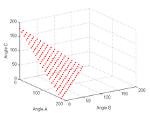
Imagine that you are measuring three angles of a triangle with a protractor. From the first trial, you got values [30.5, 60.0, 90.1] degrees. Which are not perfect because the summation of them is not equal to 180! So, you have decided to measure angles 10 times and average them. However, still you are not sure that the sum of the averages will be 180.
Figure XXX shows the relations between three angles in a triangle.
- Method
1) Define a manifold M (e.g. Figure XXX)
2) Measure a set of values p = [a(i), b(i), c(i)] for N times
3) Compute the mean m and the covariance matrix S
4) Project p and S onto the manifold M: q, H
output:
  angles <-- q
  variance <-- f(H)
Averaging multiple observations
When you observed multiple rigid transformations for the extrinsic calibration of N sensors, you can use "Dual Quaternions" for to compute an "average" rigid transformation.
- The Algorithm
* input: {R(i), t(i)} % a set of R, t
* output: R*, t*      % optimal R, t
Procedure:
* convert all R(i), t(i) to DQ(i) % Dual Quaternions
* find the mean DQ* from {DQ(i)}
* convert DQ* to R*, t*
Dual Quaternions
"Similar to the way that rotations in 3D space can be represented by quaternions of unit length, rigid motions in 3D space can be represented by dual quaternions of unit length. This fact is used in theoretical kinematics, and in applications to 3D computer graphics, robotics and computer vision." Wiki
Working on the manifold
http://stat.fsu.edu/~anuj/CVPR_Tutorial/ShortCourse.htm Differential Geometric Methods for Shape Analysis and Activity Recognition
Registration of multiple views
Point Cloud Only
Point registration problem (1) finds point-to-point correspondences and (2) estimates the transformation between them. Previous methods can be divided into three categories: the ICP (Iterative Closest Point), soft assignment methods, and probabilistic methods.
ICP can be trapped in local minima and sensitive to initialization and the threshold to accept a match. Hence, the nearest point strategy is replaced by soft assignments within a continuous optimization framework. But, the convergence property is not guaranteed in the presence of outliers. The point-to-point assignment problem can be cast into estimation of parameters of a (Gaussian) mixture. --> EM-ICP
- ICP, EM-ICP
- Tensor
- Initialization
Source codes
- ECMPR
- EM-ICP
RGB 2D features + depth values
Since we have both RGB and depth map, registration of two views can be done by simple 3D feature matching. Given two sets of corresponding 3D feature descriptors, X = [x1, x2, ..., xn] and Y = [y1, y2, ..., yn], the rigid motion between X and Y, Y = T X, is computed directly. A robust estimation method such as RANSAC provide accurate results in the presence of outliers.
- Pseudo code: computing the rigid motion
* input: X, Y
* output: R, t

Solution = [];
For i=1:N
  randomly select 5 corresponding points from X, Y: s1 = {X(j), X(k), X(l)} and s2 = {Y(j), Y(k), Y(l)}
  estimate T' = (R', t') using s1, s2
  compute Y^ = T' X
  store the number of inliers, m(i), to Solution: S(i) = (R'(i), t'(i), m(i))
Endfor
Answer = arg max(i) (S(i).m(i))
2D, 2.5D and 3D features
Curvature estimation: HK Segmentation
- See HK Segmentation
- Curvature estimation in the presence of noise depth map
2.5D Features
- Using 2D image features on a depth map
We could use 2D image features (e.g., SIFT, ORB, SURF, LBP) on a 2.5D depth map. One of key differences is on the scale of images. Since we know absolute scale in a range map, search space can be restricted to detect only physically meaningful features.
3D Features
- maxima, spin images
Issues
- Tracking features using LKT in depth video?
How to get accurate registration?
- Depth sensor(s) should be calibrated.
- We model the uncertainties of the locations of 2D features and depth values.
- If we have a known camera matrix K, minimizing the re-projection error in image space provides an accurate estimate.
- SIM (Surface Interpenetration Measure) [Queirolo 2010]
- RGB values and depth information can be fused.
Multiple Sensor Systems
Applications
face
body
- Pose estimation and tracking
- FAAST (Skeleton tracking) from ICT@USC
- Styku body modeling
- Virtual Fitting Room
- Magic Mirror
Etc.
Related topics
Mesh representation
- From 2.5D
- From 3D
Recognition of 3D objects
feature matching methods in [Object Recognition by M. Bennamoun and G.J. Mamic]
1. Hyphothesis and test
2. Matching Relational Structures
3. Pose Clustering
4. Geometric Hashing
5. Interpretation Tree
6. Registration and Distance Transforms
Indexing for recognition
- geometric hashing
Parametric model fitting
- RANSAC, StaRSaC, ...
Appendices
Linear Algebra
vector & matrix manipulation, pseudo inverse, rank, eigen value decomposition, svd, Least Mean Squared, Homogeneous Systems
Optimization
gradient decent method, newton method, Levenberg-Marquardt (http://www.ics.forth.gr/~lourakis/levmar/), simplex
probability and statistics
covariance matrix, Bayesian probability
Filtering
- Kalman Filtering, EKF
- Particle Filtering
computational geometry
Surface Tangent, Normal, Area, Triangle mesh, Voronoi diagram, Surface Curvatures, Normal and principal curvatures
Installation: Primesense, Kinect, and Asus cameras and libraries
- OpenNI and Prime Sensor
http://www.openni.org/Downloads/OpenNIModules.aspx, choose the right version regarding your OS.
Try this: http://structure.io/openni
You need:
- OpenNI Binaries
- OpenNI Compliant Hardware Binaries for Prime Sensor Module Stable Build
After downloading and installing the binaries, you can now use the libraries of OpenNI together with OpenCV to write fantastic Codes
- Configuration in your working environment (Visual Studio)
In the "Properties" of your project, you need to add:
- DIRECTORY_OF_OPENNI\Include to your "additional include directories"
- DIRECTORY_OF_OPENNI\Lib to your "additional library directories"
- In the Linker section, under the Input node, select Additional Dependencies and add OpenNI2.lib.(should be in the DIRECTORY_OF_OPENNI\Lib\OpenNI2.lib)
- Ensure that you add the Additional Include and Library directories to both your Release and Debug configurations. Choose win32 or x64 according to the version of your OpenNI2.
- Your code files should include OpenNI.h
For your reference, check http://www.openni.org/openni-programmers-guide/
Simple Openni
https://code.google.com/p/simple-openni/wiki/Installation#Windows
How to read a single 3D point from a depth sensor? (OpenNI 2)
After you installed the OpenNI2 successfully, you should be able to run the sample programs in DIRECTORY_OF_OPENNI\Samples/Bin.
The following is the key code to get the depth information of a single point( For the initialization, you can refer to the "SimpleViewer" sample code):
openni::VideoFrameRef depthFrame;
const openni::DepthPixel* pDepth = (const openni::DepthPixel*) depthFrame.getData;
int width = depthFrame.getWidth();
int height = depthFrame.getHeight();
for (int i = 0; i < height; ++i)
    for (int j = 0; j < width; ++j, ++pDepth)
    if(i == height/2 && j == width/2 && *pDepth != 0 )//The if sentence depends on which point you want, this is the center point for example
    {} //assign the value to a 3D point structure
Display the depthMap from openNI input in the openCV image (C++) (OpenNI 1)
/* Display depth map */
// Matthias Hernandez: 07/27/2011 - University of Southern California
// m31hernandez@gmail.com
// display the depthMap from openNI input in the openCV image ‘out’
void displayDepthMap(IplImage *out, const XnDepthPixel* pDepthMap, XnDepthPixel max_depth, XnDepthPixel min_depth) {
    uchar *data = (uchar *)out->imageData;
    int step = out->widthStep;
    int channels = out->nChannels;
    float normalize = (float)(max_depth-min_depth)/255.0f;

    int index=0;
    for (int i=0; i<MAX_I; i++) {
   	 if (pDepthMap[i] < min_depth || pDepthMap[i] > max_depth) {
   		 for (int k=0; k<channels; k++)
   			 data[index++] = 0;
   	 } else {
   		 if (normalize != 0) {
   			 for (int k=0; k<channels; k++)
   				 data[index++] = (int)(255-(float)(pDepthMap[i]-min_depth)/normalize);
   		 }
   		 else
   			 for (int k=0; k<channels; k++)
   				 data[index++] = 255;
   	 }
    }

}
Display the RGB image from openNI input (C) (OpenNI 1)
/* Display image map */
// Matthias Hernandez: 07/27/2011 - University of Southern California
// m31hernandez@gmail.com
// display the image map from openNI input in the openCV image ‘out’
void displayImageMap(IplImage *out, const XnUInt8* pImageMap) {
    uchar *data = (uchar *)out->imageData;
    int step = out->widthStep;
    int channels = out->nChannels;

    for (int i=0; i<MAX3_HR; i+=3) {
   	 data[i+2]    = pImageMap[i];
   	 data[i+1]    = pImageMap[i+1];
   	 data[i]   	 = pImageMap[i+2];
    }
}
the conversion from projective to real world (C) (OpenNI 2)
#define XtoZ 1.114880018171494f
#define YtoZ 0.836160013628620f
#define MIN_DEPTH 450
#define MAX_DEPTH 800

void convertP2RW(float *pDepth, float *pReal, int x, int y, int w, int h) {
        int max_i = w * h;

	int i1 = (y * w + x),
		i2 = i1 + max_i,
		i3 = i2 + max_i;

	float Z = pDepth[i1];

    if (Z > MIN_DEPTH && Z < MAX_DEPTH){
        float X_rw = ( (float)x /(float)w -0.5f)*Z*XtoZ;
        float Y_rw = (0.5f-(float)y / (float)h)*Z*YtoZ;

		pReal[i1] = X_rw;
		pReal[i2] = Y_rw;
		pReal[i3] = Z;
	} else {
		pReal[i1] = 0.0f;
		pReal[i2] = 0.0f;
		pReal[i3] = 0.0f;
	}
}

// Of Course, the inverse function is

void convertRW2P(float *pReal, float *pDepth,int x, int y, int w, int h) {
	 int max_i = w * h;

	int i1 = (y * w + x),
	i2 = i1 + max_i,
	i3 = i2 + max_i;

	float xR = pReal[i1];
	float yR = pReal[i2];
	float zR = pReal[i3];

	int ixi = (xR/zR/XtoZ + 0.5f)*(float)w + 0.5f;  // x
	int iyi = (-yR/zR/YtoZ + 0.5f)*(float)h + 0.5f; // y

	pDepth[i1] = zR;
}
The idea of calibration (using the image of the absolute conic)
  x = P (H inv(H)) X
  H: a projective transformation
The plane at infinity and the absolute conic
PAI: fixed under H
AC: fixed under H
ADQ: fixed under H (a single equation)
 Q = H Q H’
 PAI is the null-vector of ADQ (Q a = 0)
DIAC (the dual image of the absolute conic) = the image of ADQ (cf. IAC (the image of the absolute conic))
W* = K K’ (K: the calibration matrix) by Cholesky fac.
How to read IR stream from a depth camera
http://stomatobot.com/primesense-3dsensor-ir-stream/?goback=.gde_2642596_member_242724626
References
- [Queirolo 2010] C. C. Queirolo, Luciano Silva, Olga R. P. Bellon, M. P. Segund, 3D Face Recognition using the Surface Interpenetration Measure: a Comparative Evaluation on the FRGC database, 3D Face Recognition Using Simulated Annealing and the Surface Interpenetration Measure. IEEE Trans. Pattern Anal. Mach. Intell. 32(2): 206-219 (2010).
- [CVonline] CVonline: The Evolving, Distributed, Non-Proprietary, On-Line Compendium of Computer Vision
- [Foerstner04] Uncertainty and Projective Geometry
- Computational Differential Geometry dmg.tuwien.ac.at
- Computational Geometry Algorithms Library
Depth sensors
PrimeSense www.primesense.com
Kinect - Xbox.com www.xbox.com/KINECT
Xtion PRO LIVE http://www.asus.com/Multimedia/Motion_Sensor/Xtion_PRO_LIVE/
softkinetic http://www.softkinetic.com/
velodynelidar.com http://velodynelidar.com/lidar/lidar.aspx
Introducing the Leap http://www.youtube.com/watch?v=_d6KuiuteIA
Mesa Imaging http://mesa-imaging.ch/
Tools
http://www.danielgm.net/cc/ CloudCompare - 3D point cloud and mesh processing software
http://www.cs.unc.edu/~isenburg/lastools/ LAStools: award-winning software for rapid converting, filtering, viewing, gridding, and compressing of LiDAR
Q&A
- {Put your questions here...}