This plugin uses a quartz oscillator which uses a crystal (X1), amongst other components to give a 32,768Hz (32,768=215) output. This is input to a 4020 14-Stage Ripple Counter, which divides this signal down by 214 to a 2Hz signal. This 2Hz signal is then halved in frequency using a JK flip-flop (4027) configured as a toggle flip-flop. The output from this is used as the 1Hz signal.
Both the 1Hz and 2Hz signals are taken as outputs, as the faster 2Hz signal is sometimes useful for clocking circuits at a visible speed, without going too slowly.

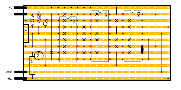
Below is the stripboard layout for the plugin. The dimensions of the stripboard are 12x23 holes. An LED and current-limiting resistor have been added to the 1Hz output to provide a visual indicator. This can be omitted without affecting the performance of the circuit. R2 may need to be mounted around D1, as there is very little space for it.
The parts lift below assumes a power supply of 9V. If a different voltage is used, it is possible that the LED current-limiting resistor (R2) must be changed and the oscillator may need adjustment as well.
| Ref. | Component |
|---|---|
| R1 | 1M Resistor, 1/4W |
| R2 | 470R Resistor, 1/4W (unless non-standard LED is used) |
| C1 | 100pF Ceramic Capacitor |
| C2 | 10pF Ceramic Capacitor |
| D1 | LED |
| X1 | 32,768Hz Quartz Crystal |
| IC1 | 40106 Schmitt Inverter IC |
| IC2 | 4020 14-Stage Binary Ripple Counter |
| IC3 | 4027 Dual JK Flip-flop |
Variations
- Any of the 4020 outputs can be used as the final output, so it could be a 4Hz oscillator, or 16Hz or even 32,768Hz. The JK flip-flop would not be necessary in this case.