Intro
An inductor is a device made from a wire conductor with several turns. This device generates a magnetic field as current passes through it similar to the magnetic field of a magnet. An inductor stores electrical energy in the form of a magnetic field.
Inductance is defined as the capability to store electrical energy in the form of a magnetic field for a given current which is directly proportional to permability, length of inductor, and number of turns and inversely proportional to cross-sectional area.

The symbol for inductance is L and is measured in Henry which has the symbol H.
Characteristics
Magnetic Field
When a voltage is applied across the inductor, current generates Electric Field . Change of Electric Field in the turns generates Magnetic Field perpendicular to Electric Field

Inductance
Inductance is the ability to generartes Magnetic Field B for a given Current

Voltage

Current

Reactance
Reactance is defined as the ratio of Voltage over current
-
- /_90


Impedance
Impedance is defined as the sum of Reactance and Resistance of Inductor . Since all conductor has Resistance
- /_Tan-1


Frequency Respond
Inductor is a device depends on frequency

- , Inductor Closed circuit, I ≠ 0
- , Capacitor Opened circuit, I = 0


- ,
- ,

![{\displaystyle Z_{L}=[R_{L}]^{\frac {1}{3}}}](../../I/m/34d8cc0bdc1b8481de8d0a1c153b328b8894529b.svg)


With the value of I at three frequency points ω = 0, 00 , 1 / CRC I - f curve can be drawn to give a picture of current in the inductor over time
Phase Angle
When a Voltage is applied across inductor, current generates magnetic field. Change in current generate change in magnetic field which generate voltage across inductor. Therefore, current will lead voltage
For ideal losses inductor which has no internal resistance, Current will lead Voltage an angle 90 . For Non - Ideal inductor which has an internal resistance, Current will lead Voltage an angle θ

Phase angle relates to time frequency or time and the value of R and L . When there is a change in phase angle Time and frequency also change


If choosing L = 1 and R = 10n then the formulas above become


Induced Voltage
Induced Voltage is defined as the voltage of the turns which oppose the current flow

Types of Inductors
Coil
For a straight wire with the following dimensions Length l, Area A, and Permitivity u and number of Turns N

Network
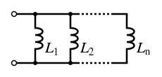
Inductors can be connected in series to increase inductance or in parallel to decrease inductance
Parallel Connection