Capacitor
Capacitor is a device that can be used to charge, discharge, or store electric energy in form of an electric field.
Capacitor's construction
A device is made from two conductive "plates" separated by a thin layer of insulation called dielectric.
Capacitor's symbol
![]()
Capacitance
Capacitance is defined as the capability of storing charge of a given voltage on each plate which is directly proportional to dielectric constant, the area of the plate and inversely proportional to the separation distance between two plates.
- = ε


Capacitance has a symbol C measured in unit farad which has symbol F.
Capacitor and electricity
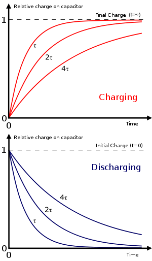
When a voltage is applied across the plates of a capacitor, charges of opposite sign will be developed across each plate until voltage across each plate equals to voltage applied, then each plate will have a charge Q and a voltage V. This process is called charging capacitor
- Q = q1 + q2 + ... =

The ratio of charge over voltage gives the capacitance of the capacitor.
At this point, when each plate has the same voltage as the applied voltage, there is no current flow in the circuit. Each plate of the capacitor has a voltage V. Capacitor stores electric energy.
If one disconnect the capacitor from the voltage source, the capacitor still has voltage V and will cause shock if touching it. Hence care must be used when disconnecting a capacitor.
If a charged capacitor is connected to ground, current starts to flow from capacitor to the ground until voltage on the capacitor equals to zero. This process is called discharging capacitor.
Characteristics
Charge
- Q = q1 + q2 + ...

Capacitance
Voltage

Current

Reactance
Reactance is defined as the ratio of voltage over current.
-
- /_-90


Impedance
Since all conductor has resistance the real capacitor's impedance is defined as the sum of reactance and resistance of capacitor.
- /_ Tan-1


Frequency respond
Capacitor is a tool depends on frequency .

- , Capacitor Opened circuit, I = 0
- , Capacitor Closed circuit, I ≠ 0


- ,
- ,


With the value of I at three frequency points ω = 0, 00 , 1 / CRC I - f curve can be drawn to give a picture of current in the capacitor over time.
Phase angle
When a voltage is applied across capacitor, it will take some time before capacitor conducts current. Therefore, current on the capacitor will lags behind voltage at an angle θ.
For ideal losses capacitor which has no internal resistance, current will lage behind voltage at an angle 90°. For non-ideal lossless capacitor which has an internal resistance, current will lage behind Voltage at an angle θ.

Phase angle relates to time frequecy or time and the value of C and RC. When there is a change in phase angle time and frequency also change. For this reason RC network is used in phase shifting.
- t = 2π Tanθ CRC

Capacitor network
Series connection

When n capacitor connected in series, the total capacitance:

When there are two capacitor of the same capacitance connected in series, the total capacitance of the two capacitors is exactly halved.
Parallel Connection
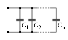
When n capacitor connected in parallel, the total capacitance

When there are two capacitor of the same capacitance connected in parallel, the total capacitance of the two capacitors is exactly doubled.
Voltage
Capacitors can only take a certain voltage across the plates before the dielectric breaks down, and current flows through the capacitor. When this happens, the capacitor is destroyed. This can involve explosion in some types of capacitors.
The common voltage limits for capacitors are:
- 10V
- 16V
- 25V
- 35V
- 63V
- 100V
- 200V
- 450V
This list is not exhaustive, and there are many capacitors with a voltage rating in between these values.
Temperature
Some capacitors contain liquid that must not be allowed to boil or freeze. These therefore have specific operating and storage temperature ranges which must not be exceeded if the capacitor is to kept intact. This is most important for electrolytic capacitors.
The common top temperature ranges for capacitors are:
- 85 °C
- 105 °C
Types of Capacitors
There are many different types of capacitors that can be used. We are most interested in electrolytic and ceramic capacitors, as they are the commonly available ones that are suitable for our level of working. For more types, see this Wikipedia article.
Ceramic Disc
Ceramic capacitors generally take the form of a disc of ceramic with two legs protruding downwards. These capacitors are not polarised - it doesn't matter which way round they are put into a circuit. The capacitances vary from a lower limit of less than 1pF, up to about 100nF. They sometimes exhibit drifting which is where capacitance changes, due to ambient conditions. This is not usually a problem, but it is something you should be aware of.
Electrolytic

Electrolytic capacitors have very large capacitance per volume unit, which makes them good for capacitances over 1μF. They take the form of cylinders which range form a few millimetres in height to several hundred. There are two main types of packaging: axial and radial. Axial capacitors are generally rarer than radial capacitors and have a lead on each end of the cylinder. Radial capacitors have both leads on the same end.
These capacitors are polarised and must be connected the right way around. The negative terminal, or cathode, is usually marked in any of the following ways:
- A stripe down the cathode side of the capacitor, usually with minus signs printed on it
- A shorter lead at the anode than at the cathode (not found on axial capacitors)
- A minus sign printed on the end of the capacitor, next to the negative lead.
Electrolytic capacitors can explode violently if they are connected incorrectly, overheat, or have too much voltage across them. Larger capacitors have vents scored into the metal ends, but they will still make a very loud noise (which can damage hearing) and spray hot electrolyte from the rupture.
They generally have poor tolerances, and are used mostly where precise capacitance is unimportant, such as for power supply smoothing, stiffening, etc.
Capacitor Labels
The markings on a capacitor usually identify the properties and safe usage parameters. The value of its capacitance is measured in farads, or metric divisions such as micro, nano, or picofarads. The markings are often encoded depending on the type of capacitor and vary by capacitor type based on room available for designation and intended use.
Electrolytic are written in decimal numbers and wester characters, for example 10uF means 10 microfarad, or 10x10^-6 farad.
Ceramic disk capacitors and certain others are marked in a number code based on the number of picofarad or 1x10^-12 farad. To decode, take the first two numbers of the 3 digit number code as the first two digits, then add a number of zero placeholders after it matching the third digit. This is now the capacitance in pF. So a 104 would be 100000pF, or 100nF. Some capacitors are marked similarly, but instead are coded in nanofarad. Manufacturers specifications would be necessary to distinguish. This type of capacitor varies its size by its capacitance and can be compared in value by size, provided the two in comparison are made of the same material.
Mica capacitors are not in common use in 2006, but are extremely stable and marked with a six spot color code. First find the arrow and view the package with it pointing right and read from top left, clockwise the six colors similar to resistor color code. First is the capacitor type, second and third are the significant digits, fourth (bottom right) is the multiplier (number of trailing zeros), fifth is the tolerance, and sixth (bottom left) is the class or characteristic code.
Safety
Capacitors can explode if overloaded or connected incorrectly. This can result in loud bang, which can damage hearing, and a spray of hot (or vapourised) electrolyte which can burn skin and damage eyesight.
Large capacitors, especially high voltage ones such as the ones in televisions can store a lethal charge on them. Always ensure that the capacitors are fully discharged before going near them.
It could happen
- A polarized radial capacitor with an aluminum cover (electrolytic) that has a curved tip is generally out of service or about to be out of order.
- A capacitor with a small black dot is usually a capacitor that has reached its breakdown voltage; that is an electric arc has passed through the dielectric and is no longer good for service.
- By discharging a charged capacitor at high capacities, it may happen to solder a conductor.